Model 1001RCM13448C Strap Settings
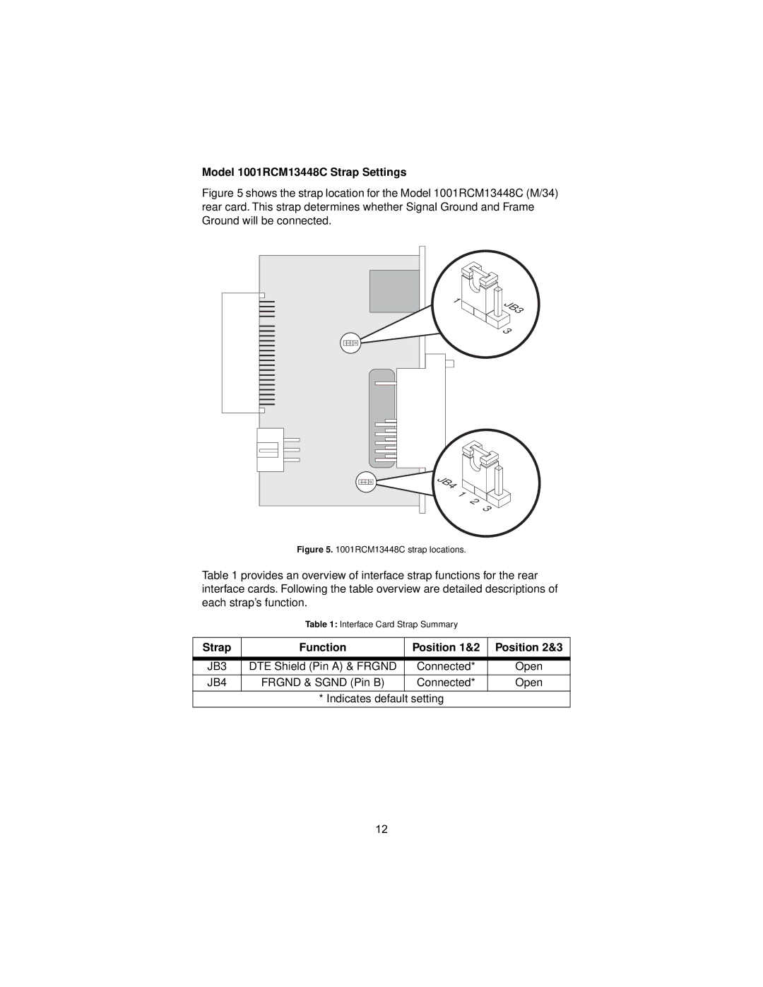
Figure 5 shows the strap location for the Model 1001RCM13448C (M/34) rear card. This strap determines whether Signal Ground and Frame Ground will be connected.
1 | JB3 |
| |
| 3 |
JB4 |
|
1 | 2 |
| |
| 3 |
Figure 5. 1001RCM13448C strap locations.
Table 1 provides an overview of interface strap functions for the rear interface cards. Following the table overview are detailed descriptions of each strap’s function.
Table 1: Interface Card Strap Summary
Strap | Function | Position 1&2 | Position 2&3 |
|
|
|
|
JB3 | DTE Shield (Pin A) & FRGND | Connected* | Open |
JB4 | FRGND & SGND (Pin B) | Connected* | Open |
|
|
|
|
* Indicates default setting
12