5.0 OPERATION
Once the 2073RC is installed and configured properly it is ready to place into operation.This section describes the function of the LED indicators, and the use of the loopback and pattern test modes.
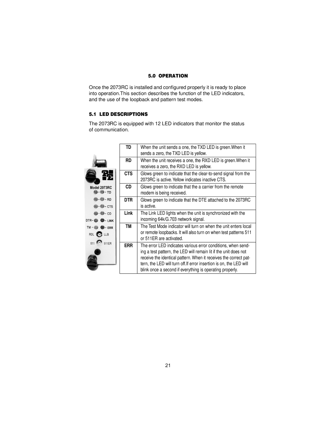
5.1 LED DESCRIPTIONS
The 2073RC is equipped with 12 LED indicators that monitor the status of communication.
TD | When the unit sends a one, the TXD LED is green.When it |
| sends a zero, the TXD LED is yellow. |
|
|
RD | When the unit receives a one, the RXD LED is green.When it |
| receives a zero, the RXD LED is yellow. |
|
|
CTS | Glows green to indicate that the |
| 2073RC is active. Yellow indicates inactive CTS. |
|
|
CD | Glows green to indicate that the a carrier from the remote |
| modem is being received. |
|
|
DTR | Glows green to indicate that the DTE attached to the 2073RC |
| is active. |
|
|
Link | The Link LED lights when the unit is synchronized with the |
| incoming 64k/G.703 network signal. |
|
|
TM | The Test Mode indicator will turn on when the unit enters local |
| or remote loopbacks. It will also turn on when test patterns 511 |
| or 511ER are activated. |
|
|
ERR | The error LED indicates various error conditions, when send- |
| ing a test pattern, the LED will remain lit if the unit does not |
| receive the identical pattern. When it receives the correct pat- |
| tern, the LED will turn off.If error insertion is on, the LED will |
| blink once a second if everything is operating properly. |
|
|
21