Operating Remote Digital Loopback (RDL)
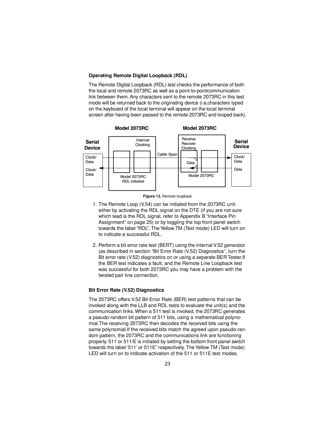
The Remote Digital Loopback (RDL) test checks the performance of both the local and remote 2073RC as well as a
Figure 13. Remote loopback
1.The Remote Loop (V.54) can be initiated from the 2073RC unit: either by activating the RDL signal on the DTE (if you are not sure which lead is the RDL signal, refer to Appendix B “Interface Pin Assignment” on page 25) or by toggling the top front panel switch towards the label “RDL”. The Yellow TM (Test mode) LED will turn on to indicate a successful RDL.
2.Perform a bit error rate test (BERT) using the internal V.52 generator (as described in section “Bit Error Rate (V.52) Diagnostics”, turn the Bit error rate (V.52) diagnostics on or using a separate BER Tester.If the BER test indicates a fault, and the Remote Line Loopback test was successful for both 2073RC you may have a problem with the twisted pair line connection.
Bit Error Rate (V.52) Diagnostics
The 2073RC offers V.52 Bit Error Rate (BER) test patterns that can be invoked along with the LLB and RDL tests to evaluate the unit(s) and the communication links. When a 511 test is invoked, the 2073RC generates a
23