3.0PPP Operational Background

PPP is a protocol used for multi-plexed transport over a point- to-point link. PPP operates on all full duplex media, and is a sym- metric peer-to-peer protocol, which can be broken into three main components: 1. A standard method to encapsulate datagrams over serial links; 2. A Link Control Protocol (LCP) to establish, con- figure, and test the data-link connection; 3. A family of Network Control Protocols (NCPs) to establish and configure different net- work layer protocols.

In order to establish communications over a point-to-point link, each end of the PPP link must first announce its capabilities and agree on the parameters of the link’s operation. This exchange is facilitated through LCP Configure-Request packets.

Once the link has been established and optional facilities have been negotiated, PPP will attempt to establish a network protocol. PPP will use Network Control Protocol (NCP) to choose and con- figure one or more network layer protocols. Once each of the net- work layer protocols have been configured, datagrams from the established network layer protocol can be sent over the link. The link will remain configured for these communications until explicit LCP or NCP packets close the link down, or until some external event occurs.

The PPP Bridging Control Protocol (BCP), defined in RFC 1638, configures and enables/disables the bridge protocol on both ends of the point-to-point link. BCP uses the same packet exchange mechanism as the Link Control Protocol (LCP). BCP is a Network Control Protocol of PPP, bridge packets may not be exchanged until PPP has reached the network layer protocol phase.

3.1 APPLICATIONS

Patton

2720Router

Bridge

Ethernet LAN

PEC Device w/ Serial I/F

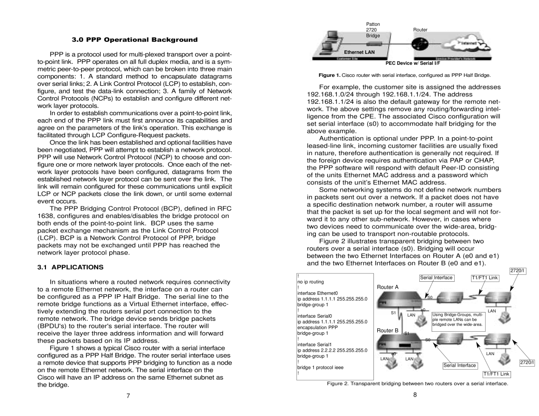
Figure 1. Cisco router with serial interface, configured as PPP Half Bridge.

For example, the customer site is assigned the addresses 192.168.1.0/24 through 192.168.1.1/24. The address 192.168.1.1/24 is also the default gateway for the remote net- work. The above settings remove any routing/forwarding intel- ligence from the CPE. The associated Cisco configuration will set serial interface (s0) to accommodate half bridging for the above example.

Authentication is optional under PPP. In a point-to-point leased-line link, incoming customer facilities are usually fixed in nature, therefore authentication is generally not required. If the foreign device requires authentication via PAP or CHAP, the PPP software will respond with default Peer-ID consisting of the units Ethernet MAC address and a password which consists of the unit’s Ethernet MAC address.

Some networking systems do not define network numbers in packets sent out over a network. If a packet does not have a specific destination network number, a router will assume that the packet is set up for the local segment and will not for- ward it to any other sub-network. However, in cases where two devices need to communicate over the wide-area, bridg- ing can be used to transport non-routable protocols.

Figure 2 illustrates transparent bridging between two routers over a serial interface (s0). Bridging will occur between the two Ethernet Interfaces on Router A (e0 and e1) and the two Ethernet Interfaces on Router B (e0 and e1).

In situations where a routed network requires connectivity to a remote Ethernet network, the interface on a router can be configured as a PPP IP Half Bridge. The serial line to the remote bridge functions as a Virtual Ethernet interface, effec-

!

no ip routing

!

interface Ethernet0

ip address 1.1.1.1 255.255.255.0 bridge-group 1

2720/I

Serial Interface

T1/FT1 Link

Router A

S0

tively extending the routers serial port connection to the

!

S1

e0

LAN

remote network. The bridge device sends bridge packets (BPDU's) to the router's serial interface. The router will receive the layer three address information and will forward these packets based on its IP address.

Figure 1 shows a typical Cisco router with a serial interface

interface Serial0

ip address 1.1.1.1 255.255.255.0 encapsulation PPP bridge-group 1

!

interface Serial1

Router B

LAN

S1

S0

Using Bridge-Groups, multi- ple remote LANs can be bridged over the wide-area.

configured as a PPP Half Bridge. The router serial interface uses

ip address 2.2.2.2 255.255.255.0 bridge-group 1

e0e1

LAN LAN

LAN

a remote device that supports PPP bridging to function as a node on the remote Ethernet network. The serial interface on the

!

bridge 1 protocol ieee

Serial Interface

2720/I

Cisco will have an IP address on the same Ethernet subnet as

!

T1/FT1 Link

the bridge.

Figure 2. Transparent bridging between two routers over a serial interface.

7

8

Page 5
Image 5
Patton electronic 2720 user manual Applications

2720 specifications

The Patton Electronics 2720 is a versatile and robust solution designed for various networking applications. It serves as a high-performance Ethernet over Copper (EoC) device, enabling the extension of Ethernet connectivity over existing copper lines. This product is particularly beneficial for businesses and organizations looking to enhance their network infrastructure without significant investment in new cabling.

One of the main features of the Patton 2720 is its ability to support multiple Ethernet standards, including 10/100/1000BASE-T. This flexibility allows users to seamlessly integrate the device into an existing network setup, accommodating both legacy and modern equipment. Additionally, the 2720 comes equipped with several Ethernet ports, providing multiple connection options and facilitating the integration of various network devices.

The Patton 2720 employs advanced technologies to ensure reliable performance. It features adaptive equalization, which optimizes the signal quality over copper lines, mitigating potential issues like attenuation and interference. This ensures that even in environments with challenging conditions, users can expect stable and efficient data transmission. Furthermore, the device supports Power over Ethernet (PoE), allowing network cables to deliver both power and data to connected devices, reducing the need for additional power supplies.

In terms of characteristics, the Patton 2720 is designed with a compact form factor, making it suitable for deployment in both residential and commercial settings. Its rugged construction ensures durability, making it capable of withstanding harsh environments. The device is also easy to install and configure, with user-friendly interfaces and management options that simplify setup procedures.

Additionally, the Patton 2720 provides comprehensive network management capabilities, including SNMP support, which allows for remote monitoring and management of the device. This makes it an ideal choice for network administrators seeking robust oversight of their network infrastructure.

In conclusion, the Patton Electronics 2720 stands out as a reliable and feature-rich Ethernet over Copper solution, ideal for businesses looking to optimize their network performance while minimizing costs. Its combination of advanced technologies, flexible connectivity options, and ease of use make it a compelling choice for a wide range of applications.