SmartNode | 1 • General information |
|
|
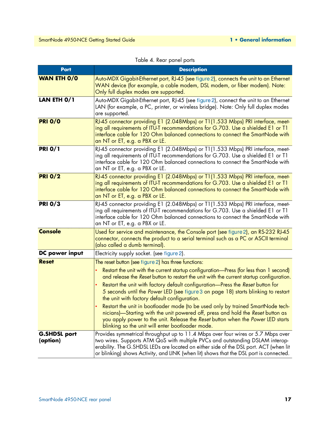
| Table 4. Rear panel ports |
|
|
Port | Description |
|
|
WAN ETH 0/0 | |
| WAN device (for example, a cable modem, DSL modem, or fiber modem). Note: |
| Only full duplex modes are supported. |
LAN ETH 0/1 | |
| LAN (for example, a PC, printer, or wireless bridge). Note: Only full duplex modes |
| are supported. |
|
|
PRI 0/0 | |
| ing all requirements of |
| interface cable for 120 Ohm balanced connections to connect the SmartNode with |
| an NT or ET, e.g. a PBX or LE. |
PRI 0/1 | |
| ing all requirements of |
| interface cable for 120 Ohm balanced connections to connect the SmartNode with |
| an NT or ET, e.g. a PBX or LE. |
|
|
PRI 0/2 | |
| ing all requirements of |
| interface cable for 120 Ohm balanced connections to connect the SmartNode with |
| an NT or ET, e.g. a PBX or LE. |
PRI 0/3 | |
| ing all requirements of |
| interface cable for 120 Ohm balanced connections to connect the SmartNode with |
| an NT or ET, e.g. a PBX or LE. |
|
|
Console | Used for service and maintenance, the Console port (see figure 2), an |
| connector, connects the product to a serial terminal such as a PC or ASCII terminal |
| (also called a dumb terminal). |
DC power input | Electricity supply socket. (see figure 2). |
|
|
Reset | The reset button (see figure 2) has three functions: |
| • Restart the unit with the current startup |
| and release the Reset button to restart the unit with the current startup configuration. |
| • Restart the unit with factory default |
| 5 seconds until the Power LED (see figure 3 on page 18) starts blinking to restart |
| the unit with factory default configuration. |
| • Restart the unit in bootloader mode (to be used only by trained SmartNode tech- |
| |
| you apply power to the unit. Release the Reset button when the Power LED starts |
| blinking so the unit will enter bootloader mode. |
G.SHDSL port | Provides symmetrical throughput up to 11.4 Mbps over four wires or 5.7 Mbps over |
(option) | two wires. Supports ATM QoS with multiple PVCs and outstanding DSLAM interop- |
| erability. The G.SHDSL LEDs are located on either side of the DSL port. ACT (when lit |
| or blinking) shows Activity, and LINK (when lit) shows that the DSL port is connected. |
|
|
SmartNode | 17 |