SmartNode | 3 • SmartNode installation |
|
|
Connecting the power supply
•Do not connect power to the AC Mains at this time.
•The external power adapter shall be a listed Limited Power
WCAUTIONRNING Source.
•The
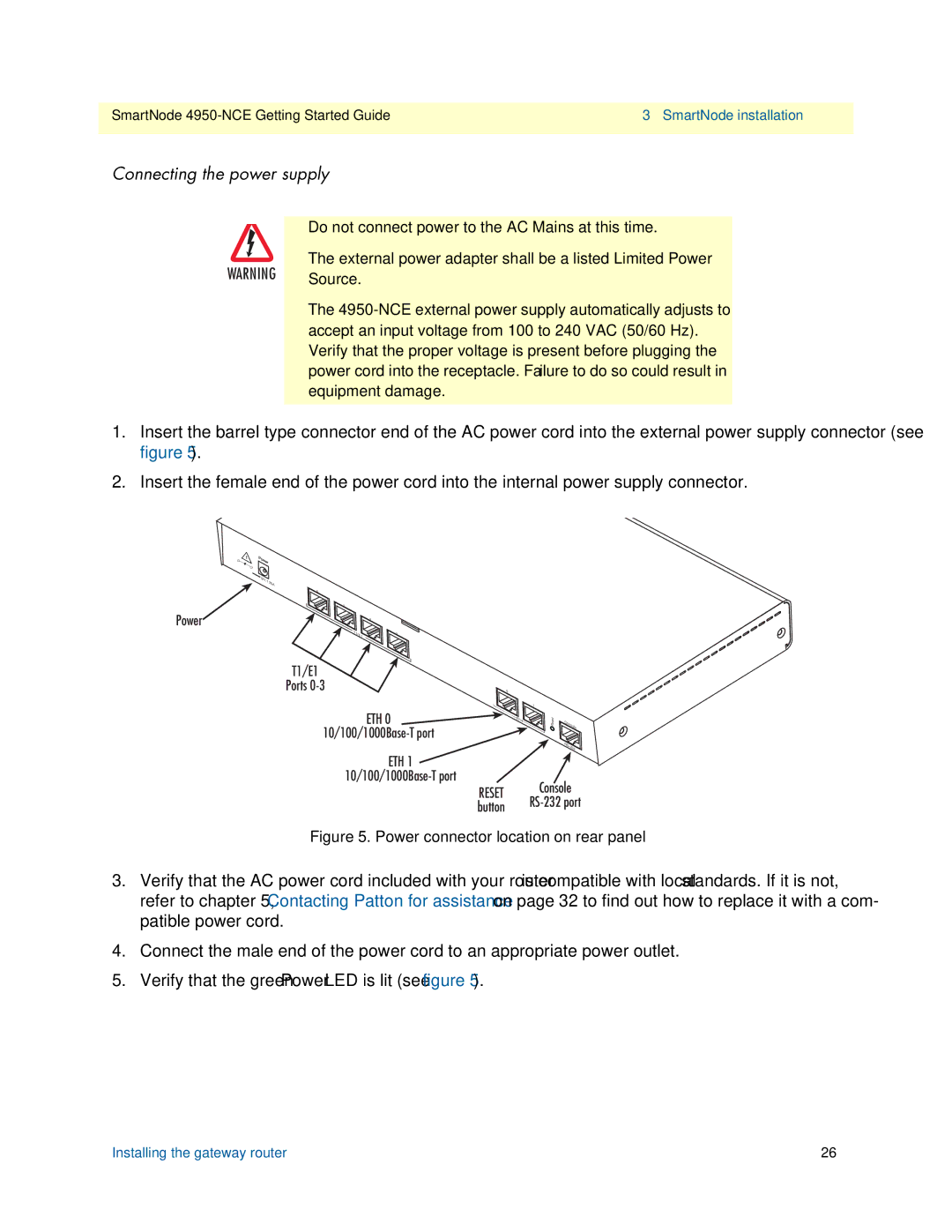
1.Insert the barrel type connector end of the AC power cord into the external power supply connector (see figure 5).
2.Insert the female end of the power cord into the internal power supply connector.
–
+
12V,1.25A
Power![]()
0 |
|
1 |
|
| 2 |
T1/E1 | 3 |
T1/E1 |
|
|
|
Ports | 0 |
|
|
ETH 0 |
| 1 |
|
ETH | Reset | Console | |
|
| ||
|
|
| |
|
|
| RS- |
|
|
| 232 |
ETH 1 |
| |
Console | ||
RESET | ||
button | ||
|
Figure 5. Power connector location on rear panel
3.Verify that the AC power cord included with your router is compatible with local standards. If it is not, refer to chapter 5, “Contacting Patton for assistance” on page 32 to find out how to replace it with a com- patible power cord.
4.Connect the male end of the power cord to an appropriate power outlet.
5.Verify that the green Power LED is lit (see figure 5).
Installing the gateway router | 26 |