If you do not have a terminal, you may force the unit to use the DIP switches as the default configuration source by turning off the unit, set- ting all the DIP switches to the ON position, then powering on the unit. This will cause the unit to enter a special mode. Then turn off the unit and change the switch settings to the desired settings. When you turn the unit on again, the unit will be set up with the selected switch set- tings.
nDS0 Channel Configuration Menu [ Bandwidth/# Channels = 2,048k/na] (default)
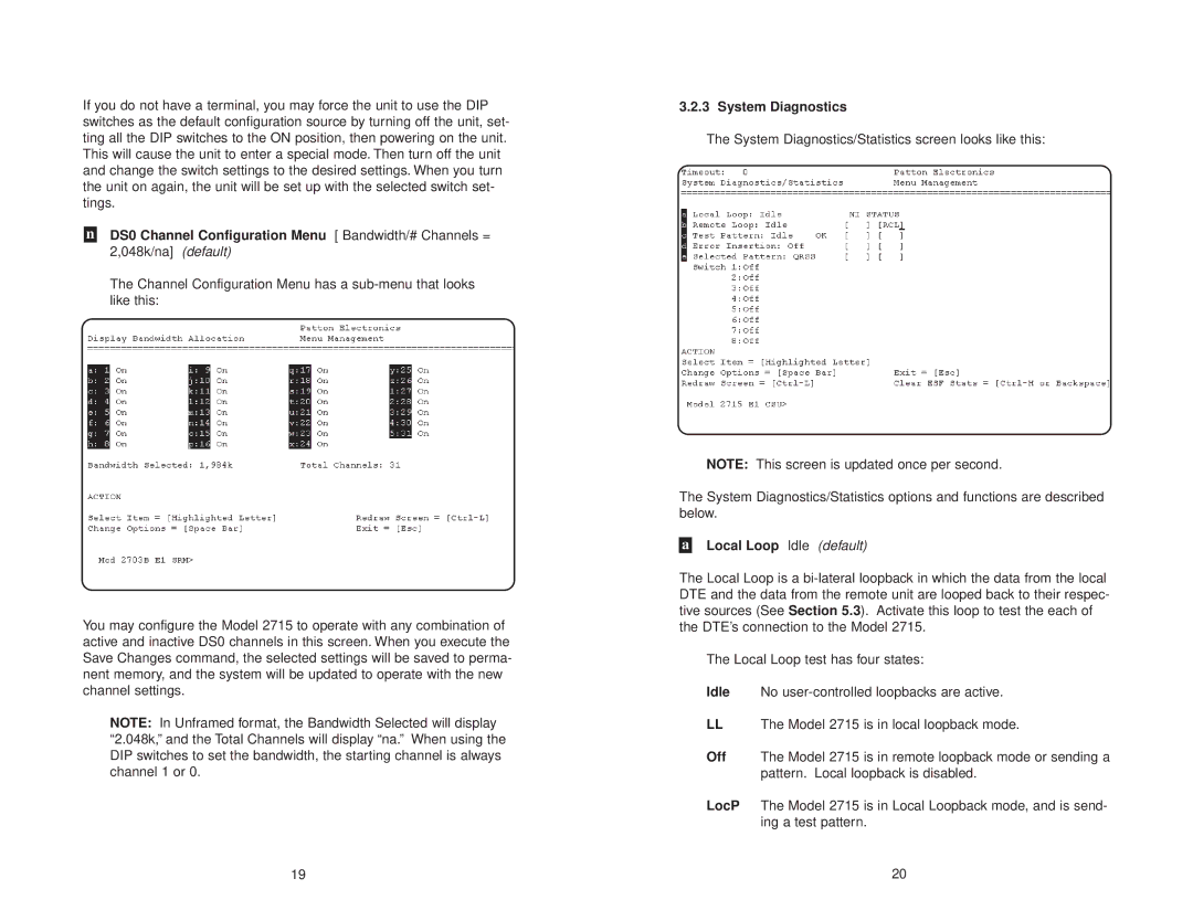
The Channel Configuration Menu has a
You may configure the Model 2715 to operate with any combination of active and inactive DS0 channels in this screen. When you execute the Save Changes command, the selected settings will be saved to perma- nent memory, and the system will be updated to operate with the new channel settings.
NOTE: In Unframed format, the Bandwidth Selected will display “2.048k,” and the Total Channels will display “na.” When using the DIP switches to set the bandwidth, the starting channel is always channel 1 or 0.
3.2.3 System Diagnostics
The System Diagnostics/Statistics screen looks like this:
NOTE: This screen is updated once per second.
The System Diagnostics/Statistics options and functions are described below.
aLocal Loop Idle (default)
The Local Loop is a
The Local Loop test has four states:
Idle No
LLThe Model 2715 is in local loopback mode.
Off The Model 2715 is in remote loopback mode or sending a pattern. Local loopback is disabled.
LocP The Model 2715 is in Local Loopback mode, and is send- ing a test pattern.
19 | 20 |
