BOILER PLACEMENT AND ASSEMBLY

2. BOILER PLACEMENT AND ASSEMBLY

A.SETTING THE BOILER

1.Provide a level foundation, located as close as possible to the center of the heating system.

2.Refer to Figure 2.2 for exploded view of boiler while checking and/or assembling parts of the boiler.

3.See clearance information in Section 1, "Preinstallation."

4.On packaged boilers, open burner mounting plate (Item 3) at this time to make certain the target wall

(Item 2) is seated in the back of the combustion chamber. Ceramic fiber blanket base liner (Item 28) should be lying flat on bottom of combustion chamber between target wall and burner.

B.OBSERVATION COVER ASSEMBLY (KNOCKDOWN BOILERS)

1.Remove observation door (Item 4) from inside burner mounting plate. Attach the observation door to the outside of the mounting plate.

C.INSTALLATION OF FLUE COLLECTOR & COVERPLATES (KNOCKDOWN BOILERS)

1.Open flue collector carton. Remove flue collector (Item 9) and high temperature rope. Lay rope (Item

8)on top of boiler against bead provided. Place flue collector on top of rope and attach to boiler with 1/4"-20 x 1-3/4" studs with nuts through flue collector brackets into the tapped lugs provided in the top of the boiler end sections. Draw nuts down snugly.

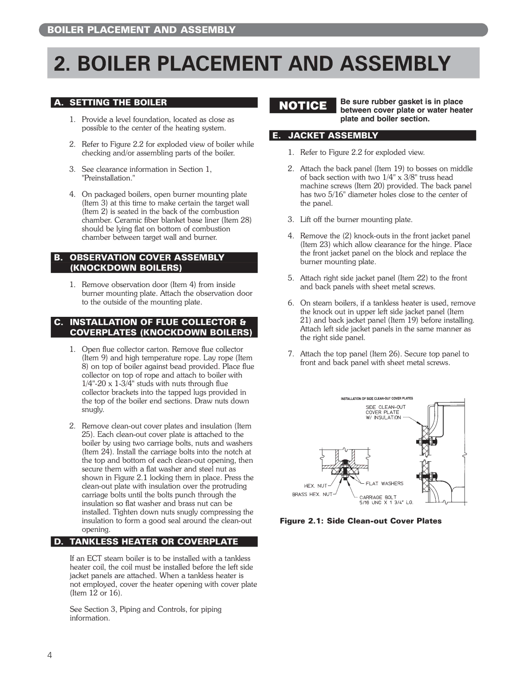
2.Remove clean-out cover plates and insulation (Item

25).Each clean-out cover plate is attached to the boiler by using two carriage bolts, nuts and washers (Item 24). Install the carriage bolts into the notch at the top and bottom of each clean-out opening, then secure them with a flat washer and steel nut as shown in Figure 2.1 locking them in place. Press the clean-out plate with insulation over the protruding carriage bolts until the bolts punch through the insulation so flat washer and brass nut can be installed. Tighten down nuts snugly compressing the insulation to form a good seal around the clean-out opening.

Be sure rubber gasket is in place NOTICE between cover plate or water heater

plate and boiler section.

E.JACKET ASSEMBLY

1.Refer to Figure 2.2 for exploded view.

2.Attach the back panel (Item 19) to bosses on middle of back section with two 1/4" x 3/8" truss head machine screws (Item 20) provided. The back panel has two 5/16" diameter holes close to the center of the panel.

3.Lift off the burner mounting plate.

4.Remove the (2) knock-outs in the front jacket panel (Item 23) which allow clearance for the hinge. Place the front jacket panel on the block and replace the burner mounting plate.

5.Attach right side jacket panel (Item 22) to the front and back panels with sheet metal screws.

6.On steam boilers, if a tankless heater is used, remove the knock out in upper left side jacket panel (Item 21) and back jacket panel (Item 19) before installing. Attach left side jacket panels in the same manner as the right side panel.

7.Attach the top panel (Item 26). Secure top panel to front and back panel with sheet metal screws.

Figure 2.1: Side Clean-out Cover Plates

D.TANKLESS HEATER OR COVERPLATE

If an ECT steam boiler is to be installed with a tankless heater coil, the coil must be installed before the left side jacket panels are attached. When a tankless heater is not employed, cover the heater opening with cover plate (Item 12 or 16).

See Section 3, Piping and Controls, for piping information.

4

Page 6
Image 6
PB Heat ECT Series manual Boiler Placement and Assembly, Setting the Boiler, Observation Cover Assembly Knockdown Boilers

ECT Series, EC Series specifications

The PB Heat EC Series and ECT Series represent a significant advancement in residential and commercial heating technology, providing reliable and efficient solutions for a variety of heating applications. These series are designed to meet the needs of homeowners and businesses seeking dependable heating while also prioritizing energy efficiency and comfort.

One of the standout features of the EC Series and ECT Series is their advanced engineering, which includes a range of high-efficiency boilers. These units utilize a cast iron heat exchanger that ensures excellent thermal transfer and durability. The cast iron construction is known for its longevity, enabling these boilers to withstand high temperatures and pressures, which is essential for long-term performance and reliability.

In terms of efficiency, both series feature energy-saving technologies that comply with the latest environmental standards. The EC Series, for example, boasts an impressive Annual Fuel Utilization Efficiency (AFUE) rating, indicating that a significant portion of the fuel consumed is converted into usable heat. This results in lower fuel bills and a reduced carbon footprint. The ECT Series further enhances efficiency with features like modulating burners that adjust the heat output based on demand, providing optimal comfort while minimizing energy waste.

Another notable characteristic of these series is their user-friendly controls and digital interfaces. The boilers come equipped with intuitive controls that allow homeowners to easily set and monitor their heating preferences. Many units also support advanced features, including Wi-Fi connectivity, enabling users to manage their heating systems remotely via smartphone applications.

In addition to their efficiency and user-friendly design, the PB Heat EC and ECT Series prioritize safety. These boilers incorporate multiple safety features, such as pressure relief valves and low water cut-off mechanisms, which help prevent operational hazards and ensure safe operation.

Overall, the PB Heat EC Series and ECT Series offer a robust combination of advanced heating technologies, efficiency, and safety. With their durable construction, energy-saving capabilities, and user-friendly controls, these heating solutions are ideal for those looking to invest in reliable and efficient heating systems. Whether for a residential property or a commercial facility, the EC and ECT Series stand out as exceptional choices in the modern heating landscape.