F R O N T P A N E L
5
6 | 7 | 4 | 8 | 9 |
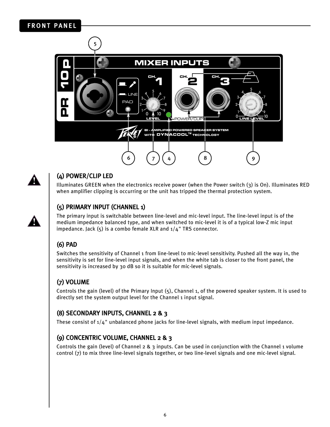
(4) POWER/CLIP LED
Illuminates GREEN when the electronics receive power (when the Power switch (3) is On). Illuminates RED when amplifier clipping is occurring or the unit has tripped the thermal protection system.
(5) PRIMARY INPUT (CHANNEL 1)
The primary input is switchable between
(6) PAD
Switches the sensitivity of Channel 1 from
(7) VOLUME
Controls the gain (level) of the Primary Input (5), Channel 1, of the powered speaker system. It is used to directly set the system output level for the Channel 1 input signal.
(8) SECONDARY INPUTS, CHANNEL 2 & 3
These consist of 1/4" unbalanced phone jacks for
(9) CONCENTRIC VOLUME, CHANNEL 2 & 3
Controls the gain (level) of Channel 2 & 3 inputs. Can be used in conjunction with the Channel 1 volume control (7) to mix three
6
