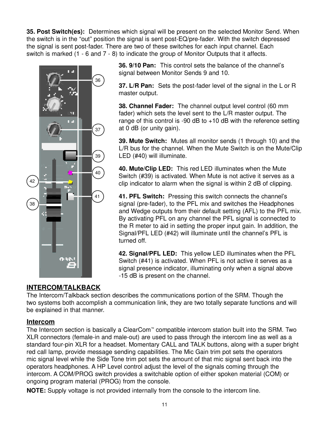
35.Post Switch(es): Determines which signal will be present on the selected Monitor Send. When the switch is in the “out” position the signal is sent
switch is marked (1 - 6 and 7 - 8) to indicate the group of Monitor Outputs that it affects.
36
37
39 |
40
42
41
38
INTERCOM/TALKBACK
36.9/10 Pan: This control sets the balance of the channel’s signal between Monitor Sends 9 and 10.
37.L/R Pan: Sets the
38.Channel Fader: The channel output level control (60 mm fader) which sets the level sent to the L/R master output. The range of this control is
39.Mute Switch: Mutes all monitor sends (1 through 10) and the L/R bus for the channel. When the Mute Switch is on the Mute/Clip LED (#40) will illuminate.
40.Mute/Clip LED: This red LED illuminates when the Mute Switch (#39) is activated. When Mute is not active it serves as a clip indicator to alarm when the signal is within 2 dB of clipping.
41.PFL Switch: Pressing this switch connects the channel’s signal
42.Signal/PFL LED: This yellow LED illuminates when the PFL Switch (#41) is activated. When PFL is not active it serves as a signal presence indicator, illuminating only when a signal above
The Intercom/Talkback section describes the communications portion of the SRM. Though the
two systems both accomplish a communication link, they are two totally separate functions and will be explained in that manner.
Intercom
The Intercom section is basically a ClearCom™ compatible intercom station built into the SRM. Two XLR connectors
mic signal level while the Side Tone trim pot sets the amount of that mic signal sent back into the operators headphones. A HP Level control adjust the level of the signals coming through the intercom. A COM/PROG switch provides a switchable option of either spoken material (COM) or ongoing program material (PROG) from the console.
NOTE: Supply voltage is not provided internally from the console to the intercom line.
11
