19
18
17
16
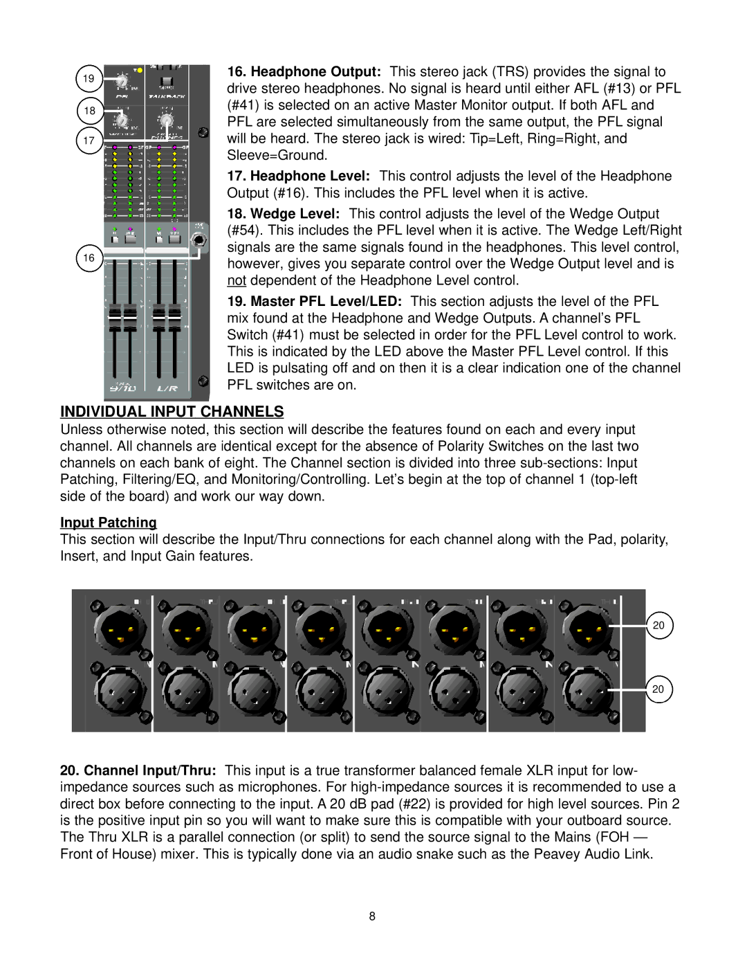
16.Headphone Output: This stereo jack (TRS) provides the signal to drive stereo headphones. No signal is heard until either AFL (#13) or PFL (#41) is selected on an active Master Monitor output. If both AFL and PFL are selected simultaneously from the same output, the PFL signal will be heard. The stereo jack is wired: Tip=Left, Ring=Right, and Sleeve=Ground.
17.Headphone Level: This control adjusts the level of the Headphone Output (#16). This includes the PFL level when it is active.
18.Wedge Level: This control adjusts the level of the Wedge Output
(#54). This includes the PFL level when it is active. The Wedge Left/Right signals are the same signals found in the headphones. This level control, however, gives you separate control over the Wedge Output level and is not dependent of the Headphone Level control.
19.Master PFL Level/LED: This section adjusts the level of the PFL mix found at the Headphone and Wedge Outputs. A channel’s PFL Switch (#41) must be selected in order for the PFL Level control to work. This is indicated by the LED above the Master PFL Level control. If this LED is pulsating off and on then it is a clear indication one of the channel PFL switches are on.
INDIVIDUAL INPUT CHANNELS
Unless otherwise noted, this section will describe the features found on each and every input channel. All channels are identical except for the absence of Polarity Switches on the last two channels on each bank of eight. The Channel section is divided into three
Input Patching
This section will describe the Input/Thru connections for each channel along with the Pad, polarity, Insert, and Input Gain features.
20
20
20.Channel Input/Thru: This input is a true transformer balanced female XLR input for low- impedance sources such as microphones. For
8
