Description by Section Index |
|
Power and Lights | 4 |
Monitor Master Section (1 thru 8, 9/10, and L/R) | 5 |
Individual Input Channel Section (1 thru 24) | 8 |
Intercom/Talkback | 11 |
In’s and Out’s | 13 |
POWER AND LIGHTS
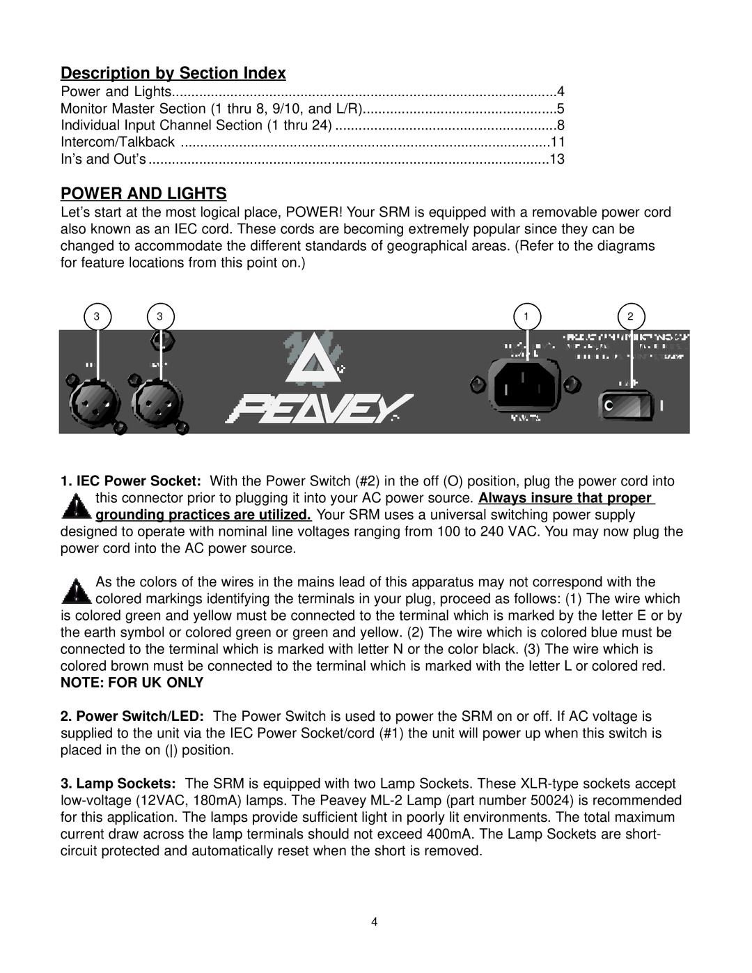
Let’s start at the most logical place, POWER! Your SRM is equipped with a removable power cord also known as an IEC cord. These cords are becoming extremely popular since they can be changed to accommodate the different standards of geographical areas. (Refer to the diagrams for feature locations from this point on.)
3 | 3 | 1 | 2 | |||
|
|
|
|
|
|
|
|
|
|
|
|
|
|
|
|
|
|
|
|
|
|
|
|
|
|
|
|
1.IEC Power Socket: With the Power Switch (#2) in the off (O) position, plug the power cord into this connector prior to plugging it into your AC power source. Always insure that proper
![]() grounding practices are utilized. Your SRM uses a universal switching power supply designed to operate with nominal line voltages ranging from 100 to 240 VAC. You may now plug the power cord into the AC power source.
grounding practices are utilized. Your SRM uses a universal switching power supply designed to operate with nominal line voltages ranging from 100 to 240 VAC. You may now plug the power cord into the AC power source.
As the colors of the wires in the mains lead of this apparatus may not correspond with the colored markings identifying the terminals in your plug, proceed as follows: (1) The wire which
is colored green and yellow must be connected to the terminal which is marked by the letter E or by the earth symbol or colored green or green and yellow. (2) The wire which is colored blue must be connected to the terminal which is marked with letter N or the color black. (3) The wire which is colored brown must be connected to the terminal which is marked with the letter L or colored red.
NOTE: FOR UK ONLY
2.Power Switch/LED: The Power Switch is used to power the SRM on or off. If AC voltage is supplied to the unit via the IEC Power Socket/cord (#1) the unit will power up when this switch is placed in the on () position.
3.Lamp Sockets: The SRM is equipped with two Lamp Sockets. These
4
