Contents
Four mixing console
Manual
Table of contents
Page
Conventions
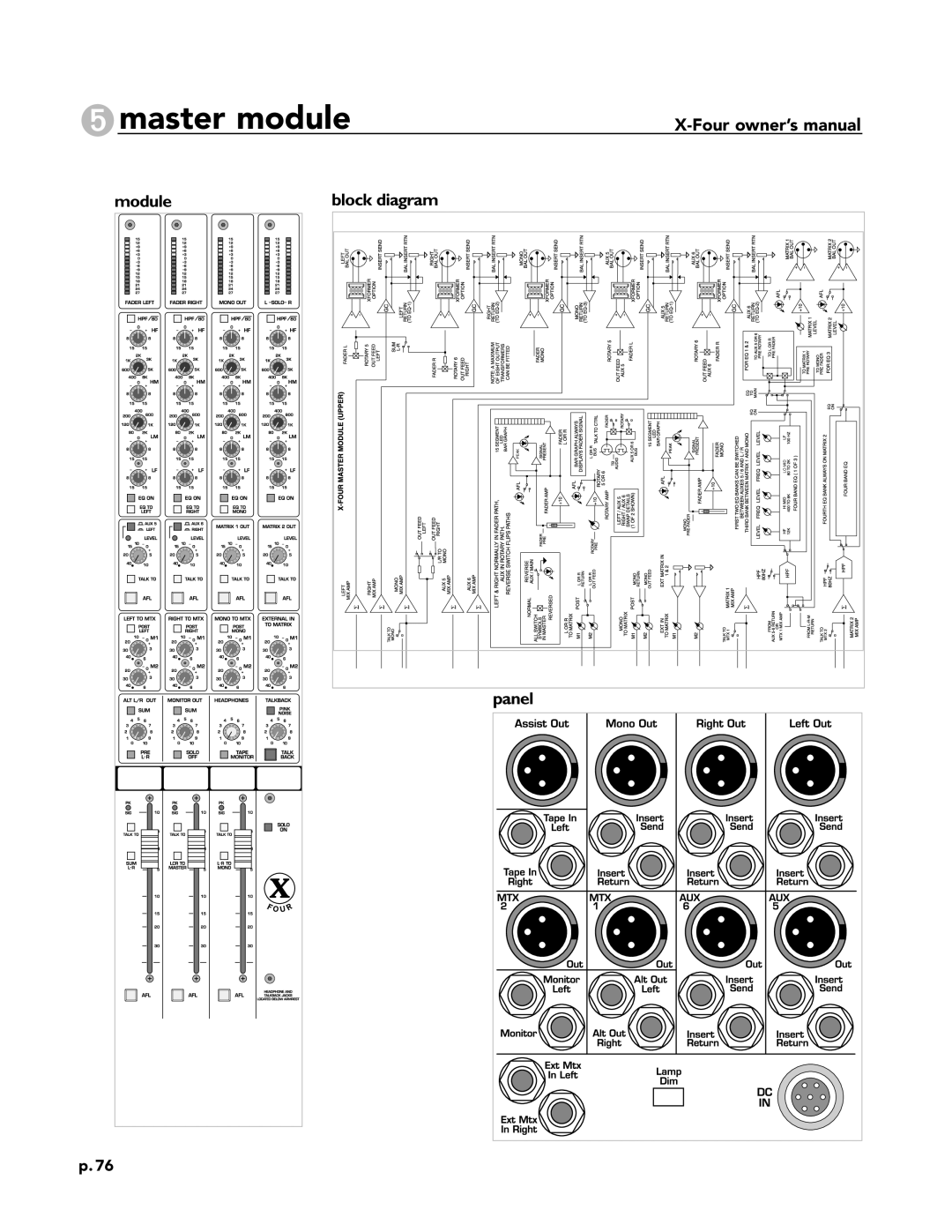
Module Block diagram Panel
Features
Phantom power-+48V
Pad
Line
Mono input module
Gain
High-pass filter-HPF
Module
EQ features
1mono input module
Aux send features
Aux sends
Aux 1-4, 5/6 pre-fader-PRE
Aux stereo 5/6
Panel
Bus assignment features
Left-center-right-LCR
Pan control
Mute
Mono input module
Mono input module
Mono input module
Level meter features
Peak indicator-PK
Signal level LED’s
Signal present indicator-SIG
Mono input module
Mono assignment-M
Left / right assignment-L-R
Group 1-4 assignment
Pre-fader listen-PFL
1mono input module
Rear panel features
Stereo input module
Left and right mono-switches
Line select-Line
Stereo input module
Input gain-GAIN
Stereo input module
Four-band stereo EQ features
Equalizer-EQ on
Panel
Aux send 1-6 controls
Stereo balance 5 and 6-STEREO
2stereo input module
Balance control
2stereo input module
Left/right assignment-L/R
2stereo input module
Balance on-groups-BAL on
2stereo input module
Line-input left and right RCA connectors
Balanced left and right line-in XLR connectors
Line-input left and right 1/4TRS jacks
Group module
Output eq features
Mid frequency-MID
Group module
Group equalization -per output channel-EQ to Group
Group module
Matrix 1-2 levels-M1, M2
Matrix features
Post-group
Panel
Fader reverse
Reversing aux / group and aux / main
Aux 1-6 output level
After-fader listen-AFL
Group module
Group assignment features
Mono assignment-fromgroup-MONO
Left/right assignment-fromgroup-L/R
Pan
Group module
Signal/peak LED’s
Group/aux level features
Fader
Panel
Group output
Group insert point
Group insert send
Group insert return
Lamp dim switch and DC in connector
Auxiliary 1-6 output XLR’s
Aux insert point
Aux insert send
Group inputs
Module Block diagram
High frequency-HF
Master module
Left,right,mono equalization-EQ to LEFT,TO RIGHT,TO Mono
Module
Post-left, post-right, post-mono
Left, right, and mono levels-MATRIX1-2
External input levels-MATRIX1-2
Panel
Master output levels-MTX1-2
Matrix output features
Matrix 1-2 talkback-TALK to
Master module
Alternate out features
Pre switch
Alternate out level
Sum mono
Master module
Monitor output features
Monitor-out level
Solo-off
Headphone level
Four Block Diagram
Left master features
Signal/peak LED-SIG/PEAK
Talkback left/right-TALK to
Sum left/right-SUM L/R
Panel
Left/center/right-LCR to Master
Right master features
Right master fader
Four Block Diagram
Mono master features
Solo on indicator
Talkback mono-TALK to Mono
Main left/ main right-L-R to Mono
Panel
Talkback features
Talkback level
Pink noise
Talkback on-TALK on
Module Block diagram
Left and right alternate output XLR’s
Left and right monitor output jacks
Matrix 1-2 output XLR’s
Left, right and mono output XLR’s
Module
DC power-in
Insert points-left, right, and mono
Model 5A power supply
Specifications
Power supply usage
Power requirements
Supply identification
Ground linking
Power supply
Redundant power supplies
Console and power supply grounding
Multiple power supplies in-series
D7000011 10 /12 /99