BLADE SHAFT ASSEMBLY
(1)
SPINDLE ![]()
HOUSING
(1)J0259 OIL SEAL
(1)
SHAFT
ASSEMBLY
(5)K1247
LOCK NUT
ROTATION
DIRECTION
(2)
PIVOT
WASHER
(1) N0152 | ! WARNING |
UPPER | |
BEARING |
STOP THE ENGINE, REMOVE BATTERY
CABLE AND SUPPORT THE DECK BEFORE
WORKING UNDERNEATH. FAILURE TO
DO SO MAY RESULT IN SERIOUS INJURY
(1) N0153
 LOWEROR DEATH. BEARING
| Figure |
| CUTTING |
| BLADE |
(1) |
|
BLADE BAR | SHARPEN AT |
(2) K0302 | 45 DEGREES |
| |
LOCK NUT |
|
(2) | Figure |
HAMMER | |
MODULE |
|
(4) |
|
CUTTING |
|
BLADE |
|
(2) | (2) |
|
PIVOT | CUTTING | ROTATION |
BUSHING | TOOTH | DIRECTION |
(2) K0298 |
|
|
(8) K0297 |
| |
SHCS |
| |
| SHCS |
|
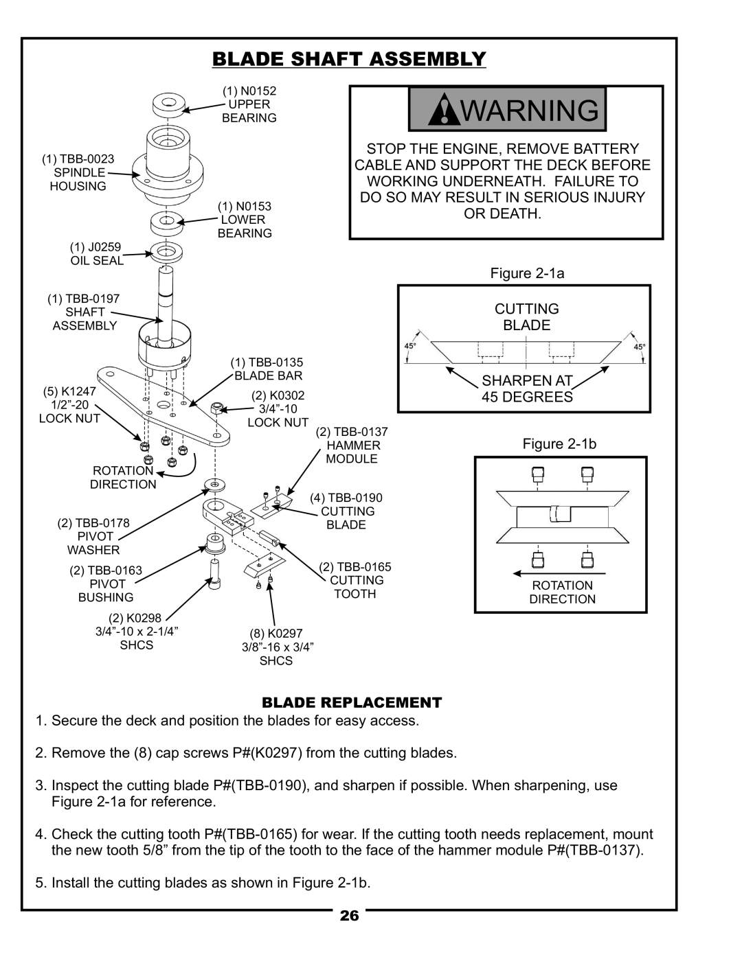
BLADE REPLACEMENT
1.Secure the deck and position the blades for easy access.
2.Remove the (8) cap screws P#(K0297) from the cutting blades.
3.Inspect the cutting blade
4.Check the cutting tooth
5.Install the cutting blades as shown in Figure
26