
C3407M-D specifications
The Pelco C3407M-D is a cutting-edge video surveillance camera designed to meet the increasingly sophisticated demands of modern security systems. Known for its reliability and high-quality performance, the C3407M-D features an array of technology and characteristics that make it a preferred choice among security professionals.One of the standout features of the C3407M-D is its high-resolution imaging capability. With a 4MP sensor, it captures crisp and detailed images, ensuring that critical moments are recorded with clarity. The camera is equipped with a wide dynamic range (WDR) technology that allows it to perform exceptionally well in challenging lighting conditions, such as when transitioning from bright to dark areas. This capability ensures that both highlights and shadows are well represented in every frame.
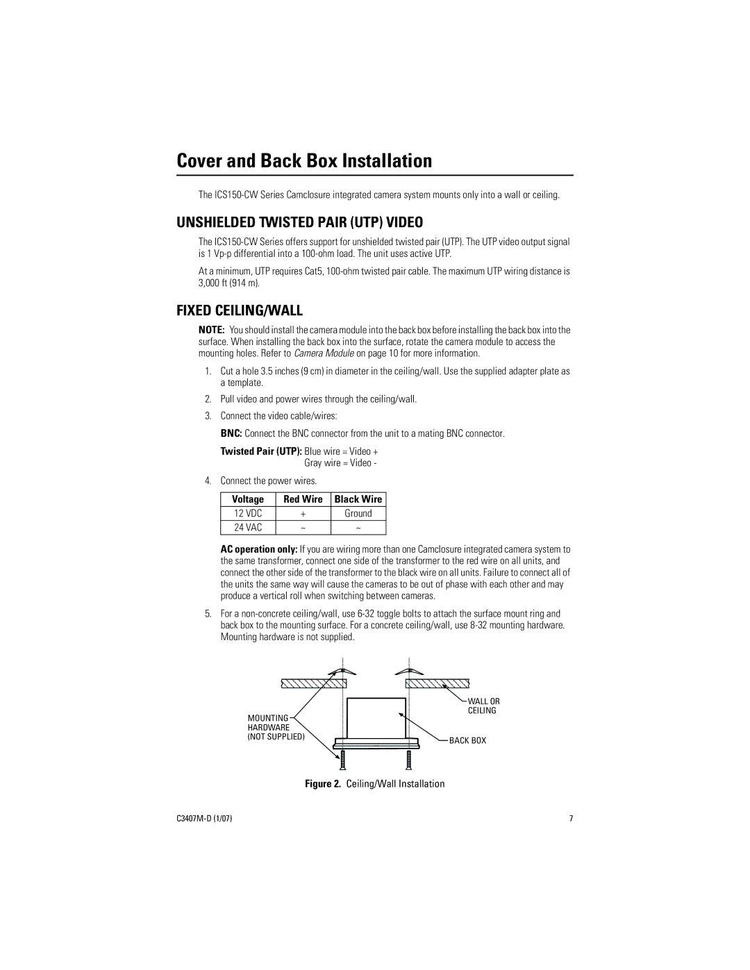
The C3407M-D offers a variety of lens options, allowing versatility depending on the specific surveillance needs. It can accommodate different focal lengths, from wide-angle for broad coverage to telephoto for more focused monitoring. This flexibility enables users to adapt the camera for various environments, whether it be a sprawling outdoor area or a confined indoor space.
Their advanced video processing algorithms further enhance the camera's performance. Features such as motion detection and tamper detection provide additional layers of security, alerting users in real-time when suspicious activities are detected. Moreover, the C3407M-D supports H.265 video compression, which ensures efficient storage and bandwidth utilization without compromising image quality.
Built for durability, the Pelco C3407M-D adheres to IP66 standards for ingress protection, making it suitable for outdoor applications even in harsh weather conditions. Its rugged design is resistant to dust and moisture, ensuring reliable operation whether installed in a cityscape, industrial environment, or remote area.
The camera integrates seamlessly with Pelco’s video management systems, allowing for easy setup, monitoring, and control. Its network capabilities ensure remote access and management, providing flexibility for users who need to monitor their environments from anywhere at any time.
In summary, the Pelco C3407M-D is a robust, high-performance surveillance camera that leverages advanced imaging technology and user-friendly features to enhance security measures across various settings. Its combination of high-resolution imaging, versatile lens options, and intelligent features makes it an excellent choice for maintaining safety and security.