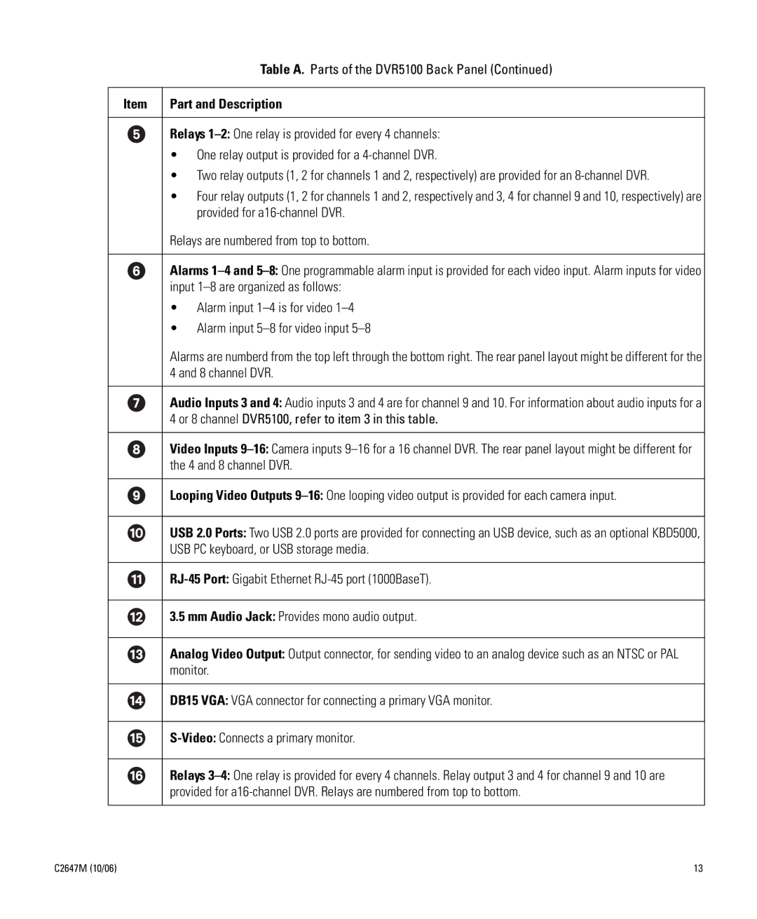
Table A. Parts of the DVR5100 Back Panel (Continued)
Item | Part and Description |
Relays
•One relay output is provided for a
•Two relay outputs (1, 2 for channels 1 and 2, respectively) are provided for an
•Four relay outputs (1, 2 for channels 1 and 2, respectively and 3, 4 for channel 9 and 10, respectively) are provided for
Relays are numbered from top to bottom.
Alarms
•Alarm input
•Alarm input
Alarms are numberd from the top left through the bottom right. The rear panel layout might be different for the 4 and 8 channel DVR.
Audio Inputs 3 and 4: Audio inputs 3 and 4 are for channel 9 and 10. For information about audio inputs for a 4 or 8 channel DVR5100, refer to item 3 in this table.
Video Inputs
Looping Video Outputs
USB 2.0 Ports: Two USB 2.0 ports are provided for connecting an USB device, such as an optional KBD5000, USB PC keyboard, or USB storage media.
3.5 mm Audio Jack: Provides mono audio output.
Analog Video Output: Output connector, for sending video to an analog device such as an NTSC or PAL monitor.
DB15 VGA: VGA connector for connecting a primary VGA monitor.
Relays
C2647M (10/06) | 13 |
