REAR PANEL
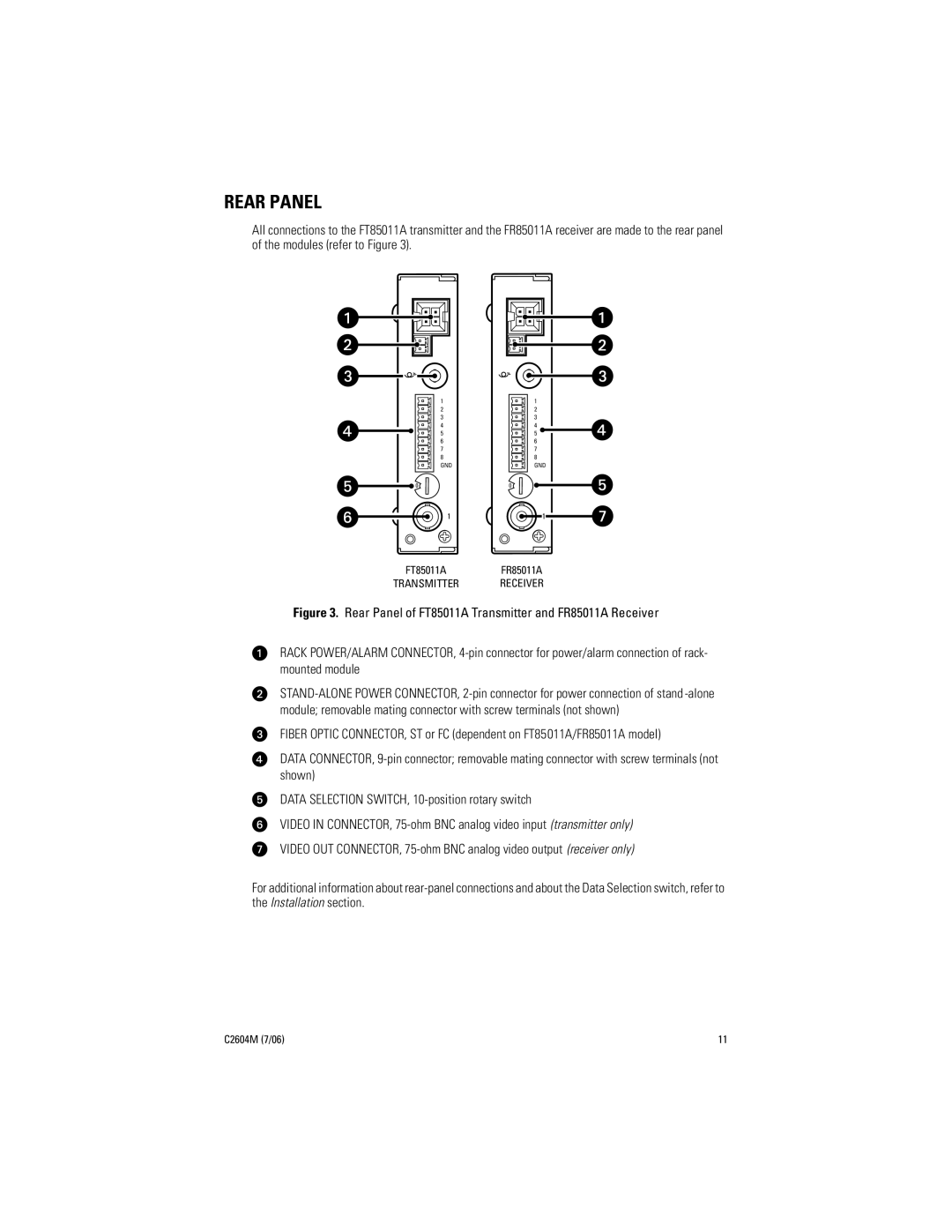
All connections to the FT85011A transmitter and the FR85011A receiver are made to the rear panel of the modules (refer to Figure 3).
|
|
| 1 |
|
|
| 2 |
|
|
| 3 |
|
|
| 4 |
|
|
| 5 |
|
|
| 6 |
|
|
| 7 |
|
|
| 8 |
|
|
| GND |
1 2 | 3 | 4 | |
0 |
|
| 5 |
9 | 8 | 7 | 6 |
|
|
| 1 |
FT85011A | |||
TRANSMITTER | |||
|
|
| 1 |
|
|
| 2 |
|
|
| 3 |
|
|
| 4 |
|
|
| 5 |
|
|
| 6 |
|
|
| 7 |
|
|
| 8 |
|
|
| GND |
1 2 | 3 | 4 | |
0 |
|
| 5 |
9 | 8 | 7 | 6 |
|
|
| 1 |
FR85011A | |||
RECEIVER | |||
Figure 3. Rear Panel of FT85011A Transmitter and FR85011A Receiver
RACK POWER/ALARM CONNECTOR, 4-pin connector for power/alarm connection of rack- mounted module
FIBER OPTIC CONNECTOR, ST or FC (dependent on FT85011A/FR85011A model)
DATA CONNECTOR,
DATA SELECTION SWITCH,
VIDEO IN CONNECTOR,
VIDEO OUT CONNECTOR,
For additional information about
C2604M (7/06) | 11 |