Installation
PACKAGE CONTENTS
The following items are supplied:
1FT85011A transmitter or FR85011A receiver
1Regulated switching power supply with four plug adapters (North American, Australian, U.K., and European configurations);
1Wall clip with two
1 FT85011A/FR85011A Fiber Transmitter and Receiver Installation manual (this manual)
DATA COMMUNICATION SETUP
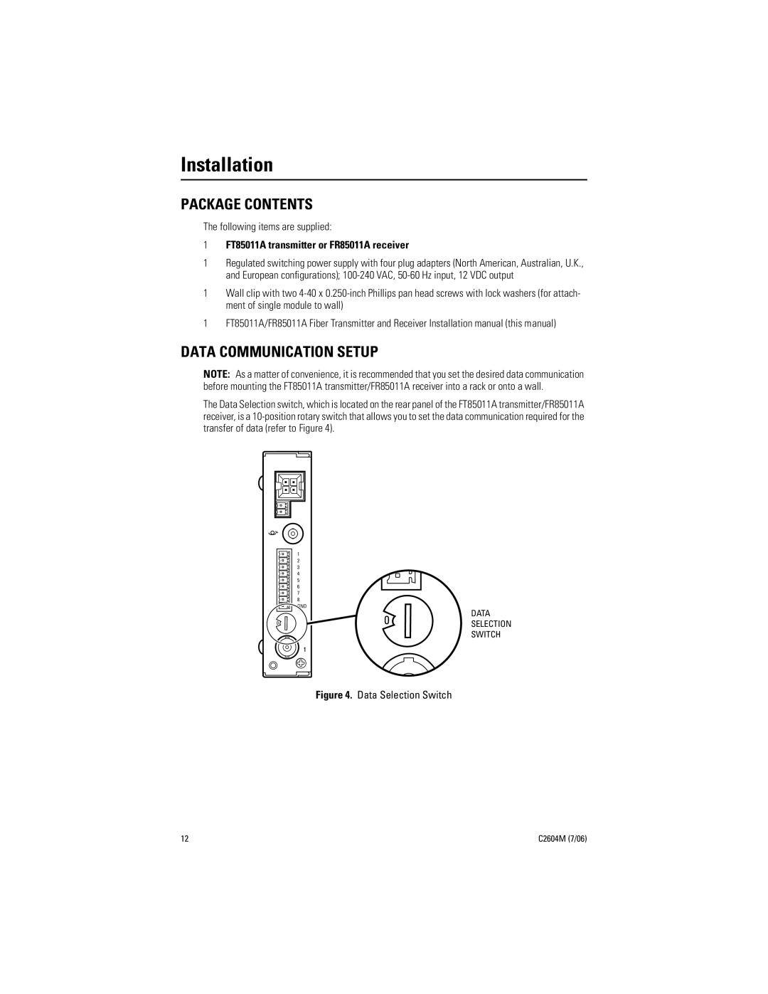
NOTE: As a matter of convenience, it is recommended that you set the desired data communication before mounting the FT85011A transmitter/FR85011A receiver into a rack or onto a wall.
The Data Selection switch, which is located on the rear panel of the FT85011A transmitter/FR85011A receiver, is a
1
2
3
4
5
6
7
8 GND
1 2 | 3 | 4 | |
0 |
|
| 5 |
9 | 8 | 7 | 6 |
1 | 2 | 3 | 4 | DATA |
|
| |||
0 |
|
| 5 | |
|
| SELECTION | ||
9 8 | 7 | 6 | SWITCH | |
Figure 4. Data Selection Switch
12 | C2604M (7/06) |