CONNECTIONS
Connections to the FT85011A transmitter and the FR85011A receiver are made on the rear panel of the modules and consist of the following:
•Power connection
NOTES:
–A 12 VDC or 24 VAC power supply can be used to power the transmitter/receiver when used as a
–In extreme temperature conditions, it is recommended that an
•Fiber connection
•Data connection
•Video input connection (transmitter only)
•Video output connection (receiver only)
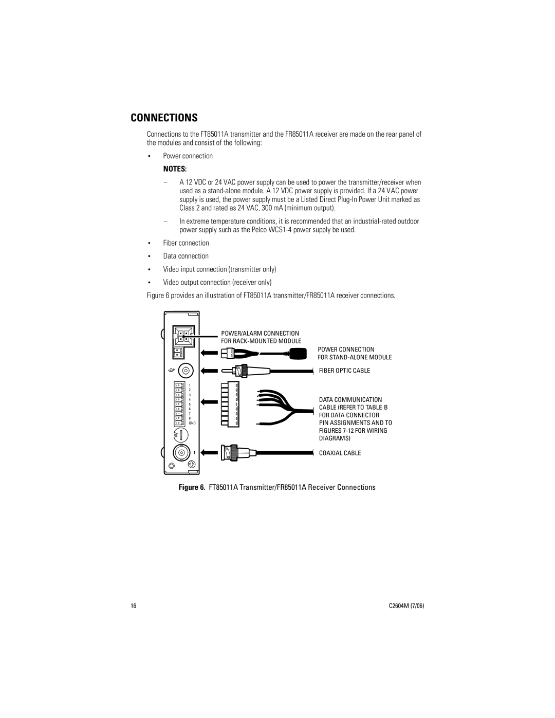
Figure 6 provides an illustration of FT85011A transmitter/FR85011A receiver connections.
1
2
3
4
5
6
7
8 GND
1 2 | 3 | 4 | |
0 |
|
| 5 |
9 | 8 | 7 | 6 |
POWER/ALARM CONNECTION
FOR
POWER CONNECTION
FOR
FIBER OPTIC CABLE
DATA COMMUNICATION
CABLE (REFER TO TABLE B
FOR DATA CONNECTOR
PIN ASSIGNMENTS AND TO
FIGURES 7-12 FOR WIRING
DIAGRAMS)
COAXIAL CABLE
Figure 6. FT85011A Transmitter/FR85011A Receiver Connections
16 | C2604M (7/06) |