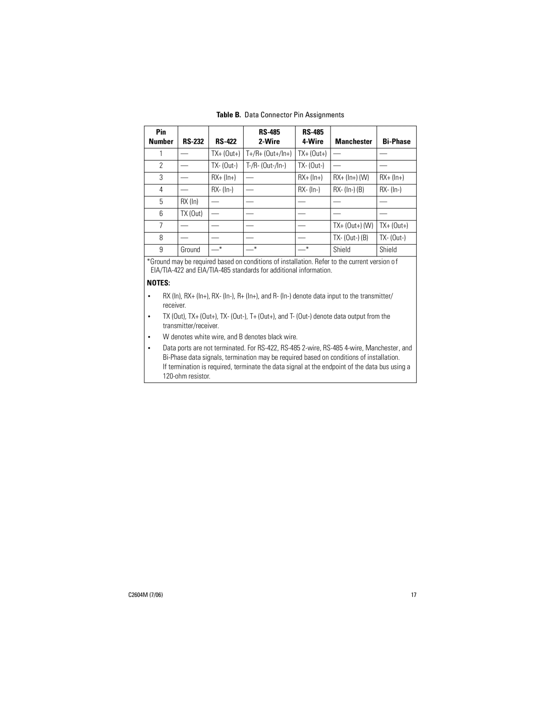
Table B. Data Connector Pin Assignments
Pin |
|
|
|
|
|
|
|
| ||
Number |
|
|
|
|
|
| Manchester |
| ||
|
|
|
|
|
|
|
|
|
|
|
1 |
| — |
| TX+ (Out+) | T+/R+ (Out+/In+) |
| TX+ (Out+) |
| — | — |
|
|
|
|
|
|
|
|
|
|
|
2 |
| — |
| TX- |
| TX- |
| — | — | |
|
|
|
|
|
|
|
|
|
|
|
3 |
| — |
| RX+ (In+) | — |
| RX+ (In+) |
| RX+ (In+) (W) | RX+ (In+) |
|
|
|
|
|
|
|
|
|
|
|
4 |
| — |
| RX- | — |
| RX- |
| RX- | RX- |
|
|
|
|
|
|
|
|
|
|
|
5 |
| RX (In) |
| — | — |
| — |
| — | — |
|
|
|
|
|
|
|
|
|
|
|
6 |
| TX (Out) |
| — | — |
| — |
| — | — |
|
|
|
|
|
|
|
|
|
|
|
7 |
| — |
| — | — |
| — |
| TX+ (Out+) (W) | TX+ (Out+) |
|
|
|
|
|
|
|
|
|
|
|
8 |
| — |
| — | — |
| — |
| TX- | TX- |
|
|
|
|
|
|
|
|
|
|
|
9 |
| Ground |
|
|
| Shield | Shield | |||
|
|
|
|
|
|
| ||||
*Ground may be required based on conditions of installation. Refer to the current version o f | ||||||||||
|
| |||||||||
NOTES: |
|
|
|
|
|
|
| |||
• | RX (In), RX+ (In+), RX- | |||||||||
| receiver. |
|
|
|
|
|
|
| ||
• | TX (Out), TX+ (Out+), TX- | |||||||||
| transmitter/receiver. |
|
|
|
|
|
| |||
• | W denotes white wire, and B denotes black wire. |
|
|
|
| |||||
• | Data ports are not terminated. For | |||||||||
| ||||||||||
| If termination is required, terminate the data signal at the endpoint of the data bus using a | |||||||||
|
|
|
|
|
|
|
| |||
|
|
|
|
|
|
|
|
|
|
|
C2604M (7/06) | 17 |