CUSTOMIZING THE COMMUNICATION LINK
The communication link between the Receiver and Hand-held Remote can be customized to prevent interference to or from other RF systems. To accomplish this, there is a 10-position configuration switch located on the Receiver circuit board and inside the Hand-held Remote. Units are shipped from the factory with all switches in the “ON” position. If you wish to change this setting, use the end of a paper clip or other blunt instrument and adjust configuration switches to match. If the configuration switch setting at the Receiver does not match that of the Hand-held Remote the communication link will not function.
Labels have been provided, marked with the most commonly used functions. These labels may be affixed to the side of the Hand-held Remote to assist with button identification.
| Affix |
| Button |
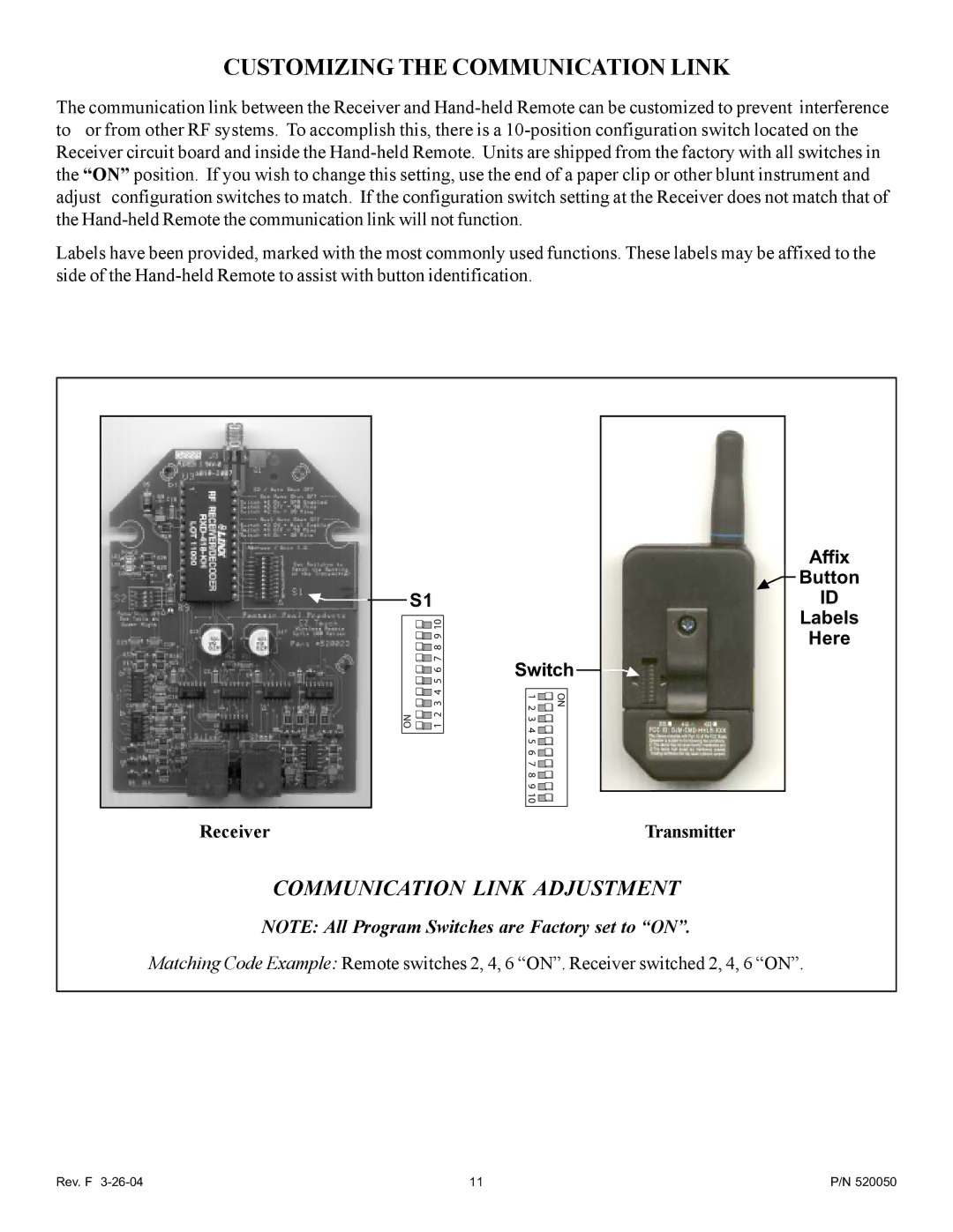
S1 | ID |
| Labels |
| Here |
| Switch |
COMMUNICATION LINK ADJUSTMENT
NOTE: All Program Switches are Factory set to “ON”.
Matching Code Example: Remote switches 2, 4, 6 “ON”. Receiver switched 2, 4, 6 “ON”.
Rev. F 3-26-04 | 11 | P/N 520050 |