CP-100 (OPTIONAL) INDOOR CONTROLLER
2 qty. separate 150 foot spools of
NOTE
Cable lubricant must be used when pulling these cables through the conduit.
Select a convenient location inside the house or other
The overall width of the Controller (with doors open) is
Remove backplate from Controller. Temporarily pull cables through large hole in backplate, and position backplate on surface of wall. Make sure that backplate is level and that “TOP” nomenclature is oriented correctly, and mark the three mounting points on the surface of the wall. With the backplate removed from the wall, drill 3/16” diameter holes and insert mounting anchors (included) into the three holes. Pull cables through large hole in backplate, and use the three
Use the Crimping Tool (model
At the
Use the four ½” screws (included) to mount
At the
Plug the short cable (attached to
Paying careful attention to match cable color to socket cable color label (silver - silver), reconnect the existing Receiver circuit board cables and the Indoor Remote cables into
Using the Crimping Tool
Make sure that the end of the cable is cut squarely (not diagonally).
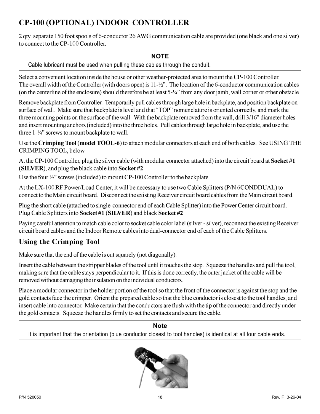
Insert the cable between the stripper blades of the tool until it touches the stop. Squeeze the handles and pull the tool, making sure that the cable stays perpendicular to it. If this is done correctly, the outer jacket of the cable will be removed without damaging the insulation on the individual conductors.
Place a modular connector in the holder portion of the tool so that the front of the connector is against the stop and the gold contacts face the crimper. Orient the prepared cable so that the blue conductor is closest to the tool handles, and insert cable into connector. Make certain that the conductors are flush with the tip of the connector and directly under the gold contacts. Squeeze the handles firmly to set the contacts and secure the cable.
Note
It is important that the orientation (blue conductor closest to tool handles) is identical at all four cable ends.
P/N 520050 | 18 | Rev. F |
