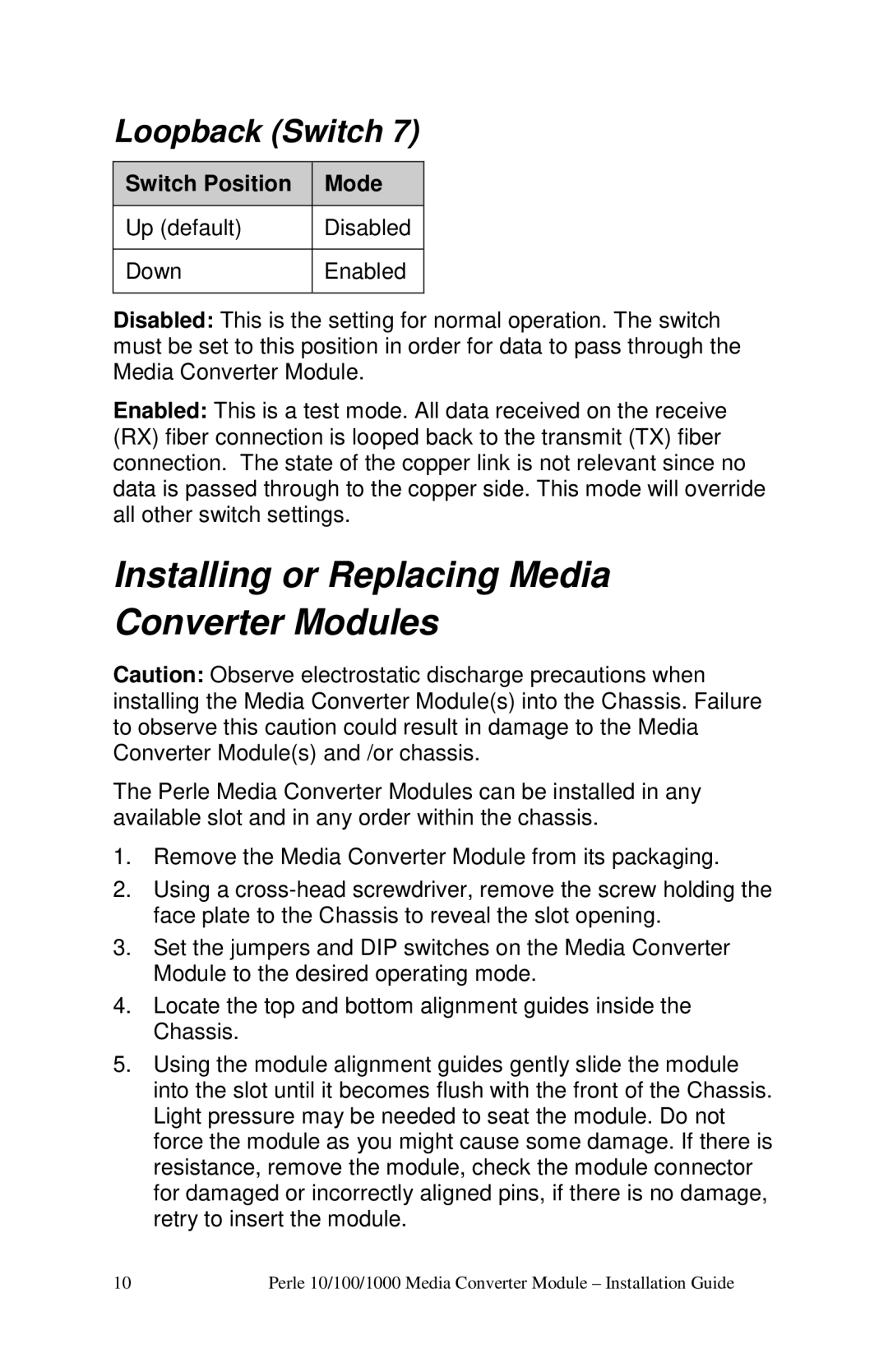
Loopback (Switch 7)
Switch Position | Mode |
|
|
Up (default) | Disabled |
|
|
Down | Enabled |
|
|
Disabled: This is the setting for normal operation. The switch must be set to this position in order for data to pass through the Media Converter Module.
Enabled: This is a test mode. All data received on the receive (RX) fiber connection is looped back to the transmit (TX) fiber connection. The state of the copper link is not relevant since no data is passed through to the copper side. This mode will override all other switch settings.
Installing or Replacing Media Converter Modules
Caution: Observe electrostatic discharge precautions when installing the Media Converter Module(s) into the Chassis. Failure to observe this caution could result in damage to the Media Converter Module(s) and /or chassis.
The Perle Media Converter Modules can be installed in any available slot and in any order within the chassis.
1.Remove the Media Converter Module from its packaging.
2.Using a
3.Set the jumpers and DIP switches on the Media Converter Module to the desired operating mode.
4.Locate the top and bottom alignment guides inside the Chassis.
5.Using the module alignment guides gently slide the module into the slot until it becomes flush with the front of the Chassis. Light pressure may be needed to seat the module. Do not force the module as you might cause some damage. If there is resistance, remove the module, check the module connector for damaged or incorrectly aligned pins, if there is no damage, retry to insert the module.
10 | Perle 10/100/1000 Media Converter Module – Instal lation Guide |
