Installation
The module comes equipped with a bank of DIP switches and jumpers for setting configuration. The default dip switch settings (all switches UP) and default jumper settings will work for most installations. For information on the management options of the
The following steps are used to configure the Perle 10/100/1000 Ethernet Media Converter Module:
1.Insert SFP Module. (SFP Models only)
2.Set the
3.Set the
4.Set the DIP switch settings (optional).
5.Insert the Media Converter Module into the chassis.
6.Connect the copper cable.
7.Connect the fiber cable.
Auto-MDIX Jumper
Note: The factory settings for
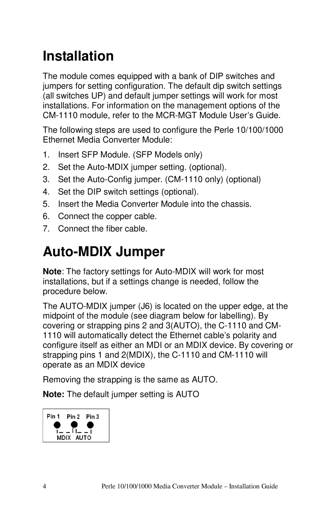
The
Removing the strapping is the same as AUTO.
Note: The default jumper setting is AUTO
4 | Perle 10/100/1000 Media Converter Module – Instal lation Guide |
