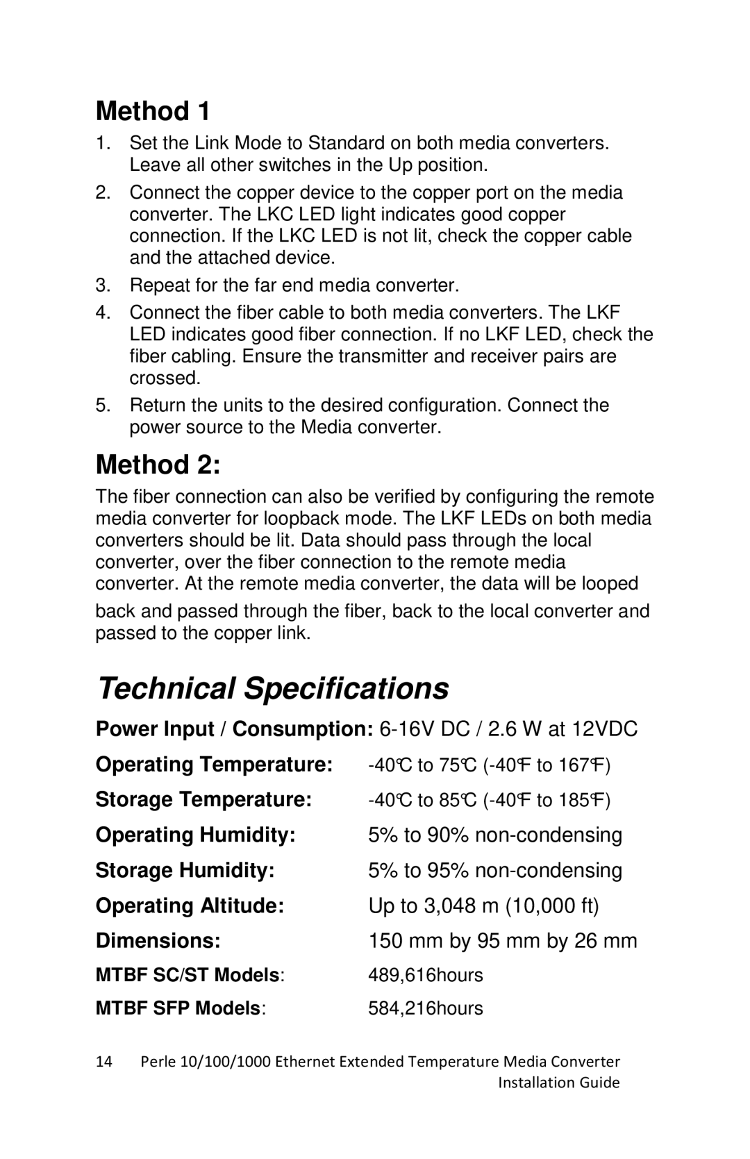
Method 1
1.Set the Link Mode to Standard on both media converters. Leave all other switches in the Up position.
2.Connect the copper device to the copper port on the media converter. The LKC LED light indicates good copper connection. If the LKC LED is not lit, check the copper cable and the attached device.
3.Repeat for the far end media converter.
4.Connect the fiber cable to both media converters. The LKF LED indicates good fiber connection. If no LKF LED, check the fiber cabling. Ensure the transmitter and receiver pairs are crossed.
5.Return the units to the desired configuration. Connect the power source to the Media converter.
Method 2:
The fiber connection can also be verified by configuring the remote media converter for loopback mode. The LKF LEDs on both media converters should be lit. Data should pass through the local converter, over the fiber connection to the remote media converter. At the remote media converter, the data will be looped
back and passed through the fiber, back to the local converter and passed to the copper link.
Technical Specifications
Power Input / Consumption:
Operating Temperature: | |
Storage Temperature: | |
Operating Humidity: | 5% to 90% |
Storage Humidity: | 5% to 95% |
Operating Altitude: | Up to 3,048 m (10,000 ft) |
Dimensions: | 150 mm by 95 mm by 26 mm |
MTBF SC/ST Models: | 489,616hours |
MTBF SFP Models: | 584,216hours |
14Perle 10/100/1000 Ethernet Extended Temperature Media Converter Installation Guide
