MONITOR FEATURES MENU CONTROLS
VGA/SVGA/HDCOMPONENT |
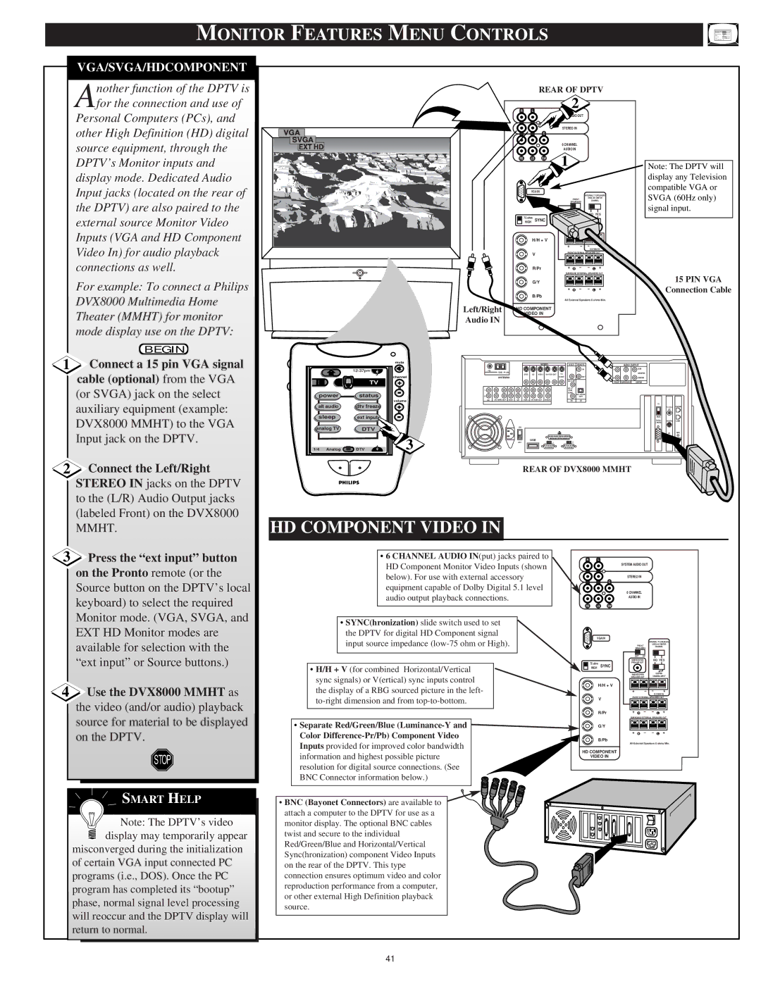
nother function of the DPTV is |
Afor the connection and use of |
Personal Computers (PCs), and |
other High Definition (HD) digital |
source equipment, through the |
VGA
![]() SVGA
SVGA ![]() EXT HD
EXT HD
REAR OF DPTV
2
R L
SYSTEM AUDIO OUT
STEREO IN
C
6 CHANNEL
AUDIO IN
DPTV’s Monitor inputs and |
display mode. Dedicated Audio |
Input jacks (located on the rear of |
the DPTV) are also paired to the |
external source Monitor Video |
Inputs (VGA and HD Component |
Video In) for audio playback |
connections as well. |
For example: To connect a Philips |
DVX8000 Multimedia Home |
Theater (MMHT) for monitor |
RS | LS | SW |
| VGA IN | |
| 75 ohm | SYNC |
| HIGH | |
| H/H + V |
| V |
| R/Pr |
| G/Y |
| B/Pb |
Left/Right | HD COMPONENT |
| VIDEO IN |
1
INTERNAL TV SPEAKERS
USED AS CENTER
FRONTCHANNEL
SPEAKERS
EXT INT
NO YES
OUT
SUBWOOFER | CENTER |
SPEAKER OUT | CHANNEL INPUT |
+ |
| – | – | + |
|
|
|
| 50 W MAX IN |
FRONT EXTERNAL SPEAKERS OUT | ||||
+ | R | – | – | L + |
SURROUND EXTERNAL SPEAKERS OUT
|
|
|
|
|
|
|
|
|
|
|
|
|
|
|
+ | R | – | – L + | |
All External Speakers 8 ohms Min.
Note: The DPTV will display any Television compatible VGA or SVGA (60Hz only) signal input.
15 PIN VGA
Connection Cable
|
| mode display use on the DPTV: |
1 |
| BEGIN |
| Connect a 15 pin VGA signal | |
|
| cable (optional) from the VGA |
|
|
|
|
| (or SVGA) jack on the select |
|
| auxiliary equipment (example: |
|
| DVX8000 MMHT) to the VGA |
|
| Input jack on the DPTV. |
|
|
|
2 | Connect the Left/Right | |
|
| STEREO IN jacks on the DPTV |
|
| to the (L/R) Audio Output jacks |
|
| (labeled Front) on the DVX8000 |
|
| mute |
|
| channel |
| TV | + |
power | status |
|
|
| volume |
alt audio | dtv freeze | + |
sleep | ext input |
|
analog TV | DTV |
|
1/4 Analog | DTV | 3 |
Audio IN
|
|
|
|
| VIDEO | MULTI | REMOTE |
| AUDIO OUTPUT |
|
| ||
FM |
|
|
|
|
|
|
| IN | L |
| SUB |
|
|
GND | AM |
|
|
|
|
|
| WOOFER |
|
| |||
|
| DSS | LD VCR 2 | TV |
|
|
|
|
| ||||
| ANTENNA |
|
|
|
| MONT | OUT | R |
| CENTER |
|
| |
|
|
|
|
|
|
|
| FRONT | SURROUND | CENTER |
|
| |
L |
|
|
|
|
|
|
|
|
|
|
|
| |
|
|
|
|
|
| PCM |
|
|
|
|
|
| |
|
|
|
|
|
|
| COAX |
|
|
|
|
| |
R |
|
|
|
|
|
|
| OPT |
|
|
|
|
|
CD | DSS | LD | VCR 2 | MULTI | IN | IN |
|
|
|
|
| ||
|
|
|
|
|
|
|
|
|
|
| TV |
|
|
|
|
|
|
|
|
|
|
|
|
|
| TV/CABLE | PHONE |
|
|
|
|
|
|
|
|
|
|
|
| ANT |
|
|
|
|
|
|
|
|
|
|
|
| RGB |
|
|
|
|
|
|
|
|
|
|
|
|
| SVGA | R DATA | LINE |
|
|
|
|
|
|
|
|
|
|
| (RGB) |
|
|
|
|
| ON |
|
|
|
|
|
|
|
|
|
|
|
|
|
|
|
|
|
|
|
|
|
| IR | MIC |
|
|
|
|
| USB |
|
|
|
|
|
|
| IN |
|
|
| OFF |
| 1 | 2 |
|
|
|
|
|
| |
|
|
|
|
|
|
|
|
|
|
| |||
REAR OF DVX8000 MMHT
MMHT. |
HD COMPONENT VIDEO IN
3 Press the “ext input” button |
on the Pronto remote (or the |
Source button on the DPTV’s local |
keyboard) to select the required |
Monitor mode. (VGA, SVGA, and |
EXT HD Monitor modes are |
available for selection with the |
“ext input” or Source buttons.) |
4 Use the DVX8000 MMHT as |
the video (and/or audio) playback |
•6 CHANNEL AUDIO IN(put) jacks paired to HD Component Monitor Video Inputs (shown below). For use with external accessory equipment capable of Dolby Digital 5.1 level audio output playback connections.
•SYNC(hronization) slide switch used to set the DPTV for digital HD Component signal input source impedance
•H/H + V (for combined Horizontal/Vertical sync signals) or V(ertical) sync inputs control the display of a RBG sourced picture in the left-
R L
C
RS LS SW
VGA IN
75 ohm
HIGH SYNC
H/H + V
V
R/Pr
SYSTEM AUDIO OUT
STEREO IN
6 CHANNEL
AUDIO IN
INTERNAL TV SPEAKERS
USED AS CENTER
FRONTCHANNEL
SPEAKERS
EXT | INT |
|
SUBWOOFER | NO YES | |
PREAMP OUT |
| |
SUBWOOFER | CENTER | |
SPEAKER OUT | CHANNEL INPUT | |
+ |
| – | – | + |
|
|
|
| 50 W MAX IN |
FRONT EXTERNAL SPEAKERS OUT | ||||
+ | R | – | – | L + |
SURROUND EXTERNAL SPEAKERS OUT
source for material to be displayed |
on the DPTV. |
STOP |
SMART HELP |
Note: The DPTV’s video |
display may temporarily appear |
misconverged during the initialization
of certain VGA input connected PC
programs (i.e., DOS). Once the PC
program has completed its “bootup”
phase, normal signal level processing
will reoccur and the DPTV display will
return to normal.
•Separate Red/Green/Blue ![]() Color
Color
Inputs provided for improved color bandwidth
information and highest possible picture resolution for digital source connections. (See BNC Connector information below.)
• BNC (Bayonet Connectors) are available to attach a computer to the DPTV for use as a monitor display. The optional BNC cables twist and secure to the individual Red/Green/Blue and Horizontal/Vertical Sync(hronization) component Video Inputs on the rear of the DPTV. This type connection ensures optimum video and color reproduction performance from a computer, or other external High Definition playback source.
G/Y
+ | R | – | – L + |
B/Pb
All External Speakers 8 ohms Min.
HD COMPONENT
VIDEO IN
41