Extended Basic Mode: This mode requires a Serial Port Adapter (see optional accessories above) to use. This mode is entered by typing an ‘E’ Character to enable the writing of parameters then a ‘P’ for Programming extended basic features. In this mode all the Basic Mode features apply as well as:
∙P1 Countdown Timer range can be extended
∙P1 and P2 adjustment pots can be bypassed and their values Hard Coded
∙The VTURNON feature can be enabled allowing the DSATX to not send a startup pulse until the engine is running
∙Parameters set via the Serial Port stay even when power is completely disconnected. They are stored in
Advanced Mode: This mode is simply going in and
*Note: modifying the temperature settings to allow higher operating temperatures will void the manufactures limited warranty.
3.3.LED Codes
∙OFF = System Off / Sleep Mode
∙ON = Running Mode, the computer starts up in this mode (does not indicate computer is on)
∙1 blinks = Main Countdown Timer
∙2 blinks = Power Down (after shutdown pulse is sent)
∙3 blinks = N/A
∙4 blinks = Over or Under Temperature Condition. (Are you using a fan?)
∙5 blinks = Power Supply Overload or Fault (ACC must go low to clear a fault)
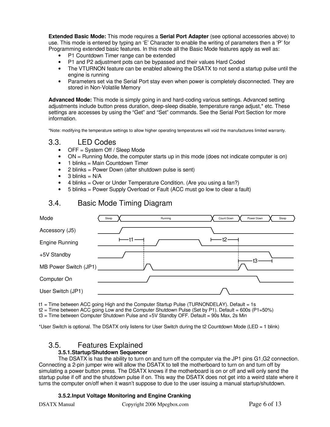
3.4.Basic Mode Timing Diagram
Mode![]() Sleep
Sleep
Accessory (J5)
Engine Running
+5V Standby
MB Power Switch (JP1) Computer On
User Switch (JP1)
t1
Running | Count Down | Power Down | Sleep |
t2
t3
t1 = Time between ACC going High and the Computer Startup Pulse (TURNONDELAY). Default = 1s
t2 = Time between ACC going Low and the Computer Shutdown Pulse (Set by P1). Default = 600s (P1=50%) t3 = Time between Computer Shutdown Pulse and +5V Standby OFF. Default = 90s Max, 2s Min
*User Switch is optional. The DSATX only listens for User Switch during the t2 Countdown Mode (LED = 1 blink)
3.5.Features Explained
3.5.1.Startup/Shutdown Sequencer
The DSATX is has the ability to turn on and turn off the computer via the JP1 pins G1,G2 connection. Connecting a
3.5.2.Input Voltage Monitoring and Engine Cranking
DSATX Manual | Copyright 2006 Mpegbox.com | Page 6 of 13 |
