Connecting the System
Connecting the power cord (1)
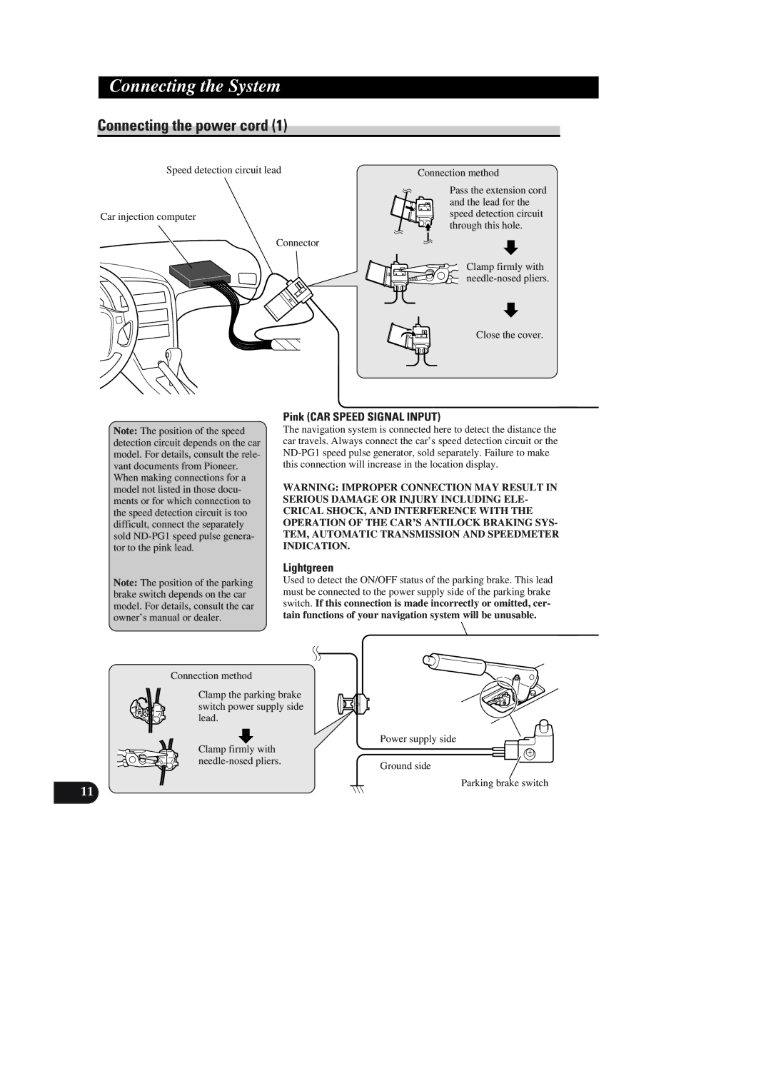
Speed detection circuit lead
Car injection computer
Connector
Connection method
Pass the extension cord and the lead for the speed detection circuit through this hole.
Clamp firmly with needle-nosed pliers.
Close the cover.
Pink (CAR SPEED SIGNAL INPUT)
Note: The position of the speed detection circuit depends on the car model. For details, consult the rele- vant documents from Pioneer. When making connections for a model not listed in those docu- ments or for which connection to the speed detection circuit is too difficult, connect the separately sold
The navigation system is connected here to detect the distance the car travels. Always connect the car’s speed detection circuit or the
WARNING: IMPROPER CONNECTION MAY RESULT IN SERIOUS DAMAGE OR INJURY INCLUDING ELE- CRICAL SHOCK, AND INTERFERENCE WITH THE OPERATION OF THE CAR’S ANTILOCK BRAKING SYS- TEM, AUTOMATIC TRANSMISSION AND SPEEDMETER INDICATION.
Lightgreen
Note: The position of the parking brake switch depends on the car model. For details, consult the car owner’s manual or dealer.
Connection method
Used to detect the ON/OFF status of the parking brake. This lead must be connected to the power supply side of the parking brake switch. If this connection is made incorrectly or omitted, cer- tain functions of your navigation system will be unusable.
Clamp the parking brake switch power supply side lead.
Clamp firmly with | Power supply side |
| |
| Ground side |
|
11