
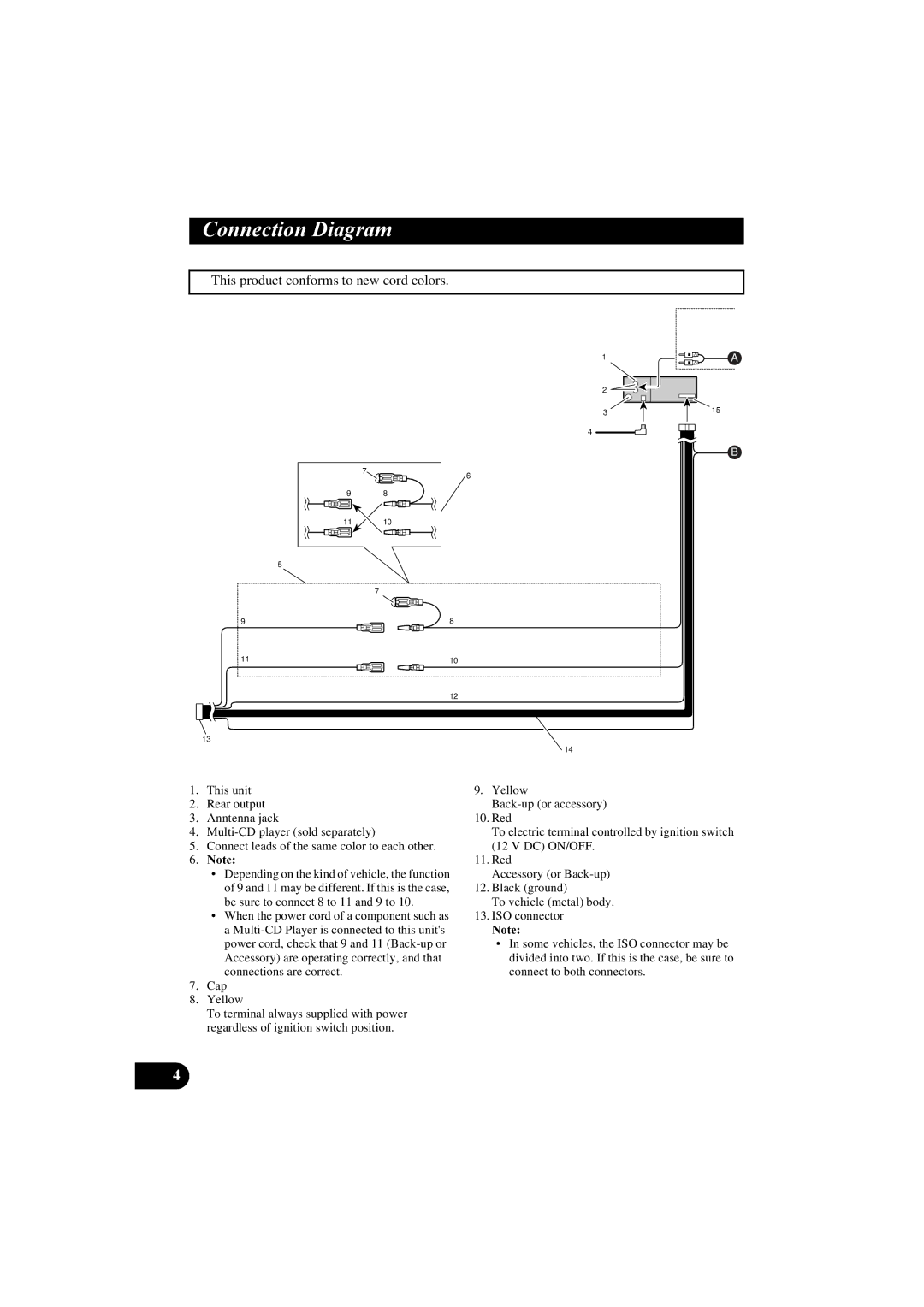
KEH-P2800R, KEH-P2830R specifications
The Pioneer KEH-P2830R and KEH-P2800R are compact car stereo receivers known for their blend of performance, versatility, and user-friendly features. Designed for both casual listeners and audiophiles, these units deliver impressive sound quality and a variety of modern functionalities that enhance the in-car audio experience.One of the main features of the KEH-P2830R is its high-quality sound processing capabilities. It comes equipped with a built-in MOSFET amplifier that outputs a robust 50 watts per channel, providing clear and powerful audio across various music genres. The receiver also includes a 3-band equalizer, allowing users to fine-tune the sound to match personal preferences and the acoustics of their vehicle.
The KEH-P2800R similarly boasts exceptional sound performance, with a powerful amplification system that guarantees clean and distortion-free audio. With its 24-bit digital-to-analog converter, this model ensures accurate sound reproduction, making every note crisp and precise.
Both units are designed with user convenience in mind. They feature a large, easy-to-read display that provides clear visibility even in bright sunlight. The rotary volume control and well-placed buttons facilitate straightforward operation, ensuring that drivers can adjust settings without distraction.
Connectivity is a key strength of the KEH-P2830R and KEH-P2800R. Each unit features multiple inputs, including USB ports and auxiliary inputs, catering to a variety of audio sources, whether it’s MP3 players, smartphones, or USB flash drives. This flexibility allows users to enjoy their favorite music from different platforms seamlessly.
The KEH-P2830R also supports CD playback and features a built-in AM/FM tuner with 24 presets, making it easy to switch between various radio stations. It also boasts compatibility with CD-R and CD-RW discs, providing even more playback options for listeners.
Both models uphold the Pioneer reputation for durability and aesthetic appeal, with sleek designs that blend well into modern vehicle interiors. Their compact size ensures easy installation in most dashboards, while the robust construction promises longevity, even in demanding environments.
In summary, the Pioneer KEH-P2830R and KEH-P2800R car stereo receivers stand out for their excellent audio quality, user-friendly design, and versatile connectivity options, making them ideal choices for enhancing any driving experience.