Connecting the Units
Note |
|
|
|
|
|
| Connecting cords with RCA pin |
| |
|
|
|
|
|
| plugs (sold separately) | Power amp | ||
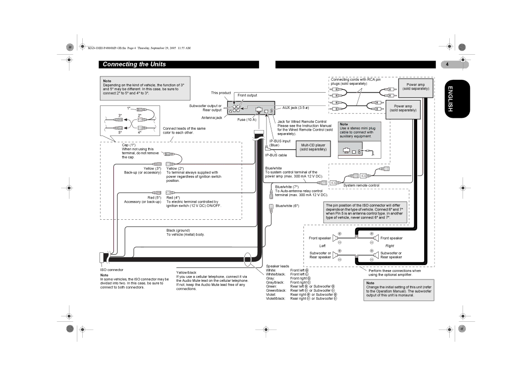
Depending on the kind of vehicle, the function of 3* |
|
|
| ||||||
and 5* may be different. In this case, be sure to |
|
|
|
| (sold separately) | ||||
connect 2* to 5* and 4* to 3*. |
|
| This product | Front output |
|
|
|
|
|
|
|
|
|
|
|
|
|
| |
|
|
| Subwoofer output or |
| AUX jack (3.5 ø) |
| Power amp | ||
|
|
| Rear output |
|
| (sold separately) | |||
|
|
|
|
|
|
| |||
|
|
| Antenna jack | Fuse (10 A) | Jack for Wired Remote Control |
|
| ||
|
|
|
| Note |
| ||||
|
|
|
|
|
| ||||
|
|
|
|
| Please see the Instruction Manual |
| |||
| Connect leads of the same |
| Use a stereo mini plug |
| |||||
|
| for the Wired Remote Control (sold |
| ||||||
| color to each other. |
| cable to connect with |
| |||||
|
| separately). |
|
| |||||
|
|
|
|
|
| auxiliary equipment. |
| ||
|
|
|
|
|
|
|
| ||
Cap (1*) |
|
|
|
|
|
|
|
| |
|
|
|
| (Blue) |
|
|
| ||
When not using this |
|
|
|
|
| (sold separately) |
|
| |
terminal, do not remove |
|
|
|
|
|
|
|
| |
the cap. |
|
|
|
|
|
|
|
| |
|
|
|
|
|
|
|
|
| |
Yellow (3*) |
| Yellow (2*) |
| Blue/white |
|
|
|
| |
| To terminal always supplied with |
| To system control terminal of the |
|
|
| |||
|
| power regardless of ignition switch |
| power amp (max. 300 mA 12 V DC). |
|
|
| ||
|
| position. |
|
|
|
| System remote control |
| |
|
|
|
|
| Blue/white (7*) |
|
| ||
|
|
|
|
| To |
|
|
| |
Red (5*) |
| Red (4*) |
| terminal (max. 300 mA 12 V DC). |
|
| |||
|
|
|
|
|
|
| |||
Accessory (or |
| To electric terminal controlled by |
|
|
| The pin position of the ISO connector will differ |
| ||
|
| ignition switch (12 V DC) ON/OFF. |
| Blue/white (6*) |
| ||||
|
|
|
|
|
|
| depends on the type of vehicle. Connect 6* and 7* |
| |
|
|
|
|
|
|
| when Pin 5 is an antenna control type. In another |
| |
|
|
|
|
|
|
| type of vehicle, never connect 6* and 7*. |
| |
|
| Black (ground) |
|
|
|
|
|
| |
|
| To vehicle (metal) body. |
|
| Front speaker | Front speaker |
| ||
|
|
|
|
|
|
| |||
|
|
|
|
|
| Left |
| Right |
|
|
|
|
|
|
| Subwoofer or | Subwoofer or |
| |
|
|
|
|
|
| Rear speaker | Rear speaker |
| |
ISO connector |
|
|
|
| Speaker leads |
|
|
|
|
|
| Yellow/black |
| White: | Front left + |
| Perform these connections when | ||
Note |
|
|
| White/black: | Front left - |
| using the optional amplifier. | ||
|
| If you use a cellular telephone, connect it via |
| ||||||
In some vehicles, the ISO connector may be | Gray: | Front right + |
|
|
| ||||
the Audio Mute lead on the cellular telephone. |
|
|
| ||||||
divided into two. In this case, be sure to |
| Gray/black: | Front right - |
| Note |
| |||
| If not, keep the Audio Mute lead free of any |
|
| ||||||
connect to both connectors. |
|
| Green: | Rear left + or Subwoofer + | Change the initial setting of this unit (refer | ||||
|
| connections. |
| ||||||
|
|
|
| Green/black: | Rear left - or Subwoofer - | to the Operation Manual). The subwoofer | |||
|
|
|
|
| |||||
|
|
|
|
| Violet: | Rear right + or Subwoofer + | output of this unit is monaural. | ||
|
|
|
|
| Violet/black: | Rear right - or Subwoofer - |
|
| |
4
ENGLISH