6Position the knife gauge over the knife as shown in Figure 24 and loosen the gib bolts until the knife is completely loose.
7Jack Screws - Using a 3mm hex wrench, rotate the jack is set correctly, it should barely touch the middle pad of enough to just hold the knife in place. Repeat Steps
screws to raise the knife setting with the rest of
or lower the knife. When the knife gauge. Snug the gib bolts tight the knives.
8Rotate the cutter head to the ends and working across
first knife you started with. Slightly tighten all the gib bolts, starting at the the cutterhead. Repeat this step on the rest of the knives.
!IMPORTANT: Sometimes the knives start to "walk" during the final tightening sequence (lift off the jack screws). Make sure the knives stay in position until final tightening is achieved.
Feed Rollers and Chip Breaker Adjustments
The infeed, outfeed rollers and chip breaker are preset at the factory for normal use. If material is not feeding evenly through the planer follow these adjustment procedures.
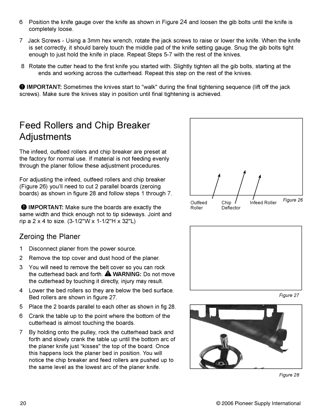
For adjusting the infeed, outfeed rollers and chip breaker (Figure 26) you’ll need to cut 2 parallel boards (zeroing boards) as shown in figure 28 and follow steps 1 through 7.
!IMPORTANT: Make sure the boards are exactly the same width and thick enough not to tip sideways. Joint and rip a 2 x 4 to size.
Outfeed | Chip | Infeed Roller | Figure 26 |
| |||
Roller | Deflector |
|
|
Zeroing the Planer
1Disconnect planer from the power source.
2Remove the top cover and dust hood of the planer.
3You will need to remove the belt cover so you can rock the cutterhead back and forth. ! WARNING: Do not move the cutterhead by touching it directly, injury may result.
4Lower the bed rollers so they are below the bed surface. Bed rollers are shown in figure 27.
5Place the 2 boards parallel to each other as shown in fig 28.
6Crank the table up to the point where the bottom of the cutterhead is almost touching the boards.
7By holding onto the pulley, rock the cutterhead back and forth and slowly crank the table up until the bottom arc of the planer knife just “kisses" the top of the board. Once this happens lock the planer bed in position. You will notice the chip breaker and feed rollers are pushed up to the same level as the lowest arc of the planer knife.
Figure 27
Figure 28
20 | © 2006 Pioneer Supply International |