Manuals
/
Pioneer
/
Home Audio
/
Stereo System
Pioneer
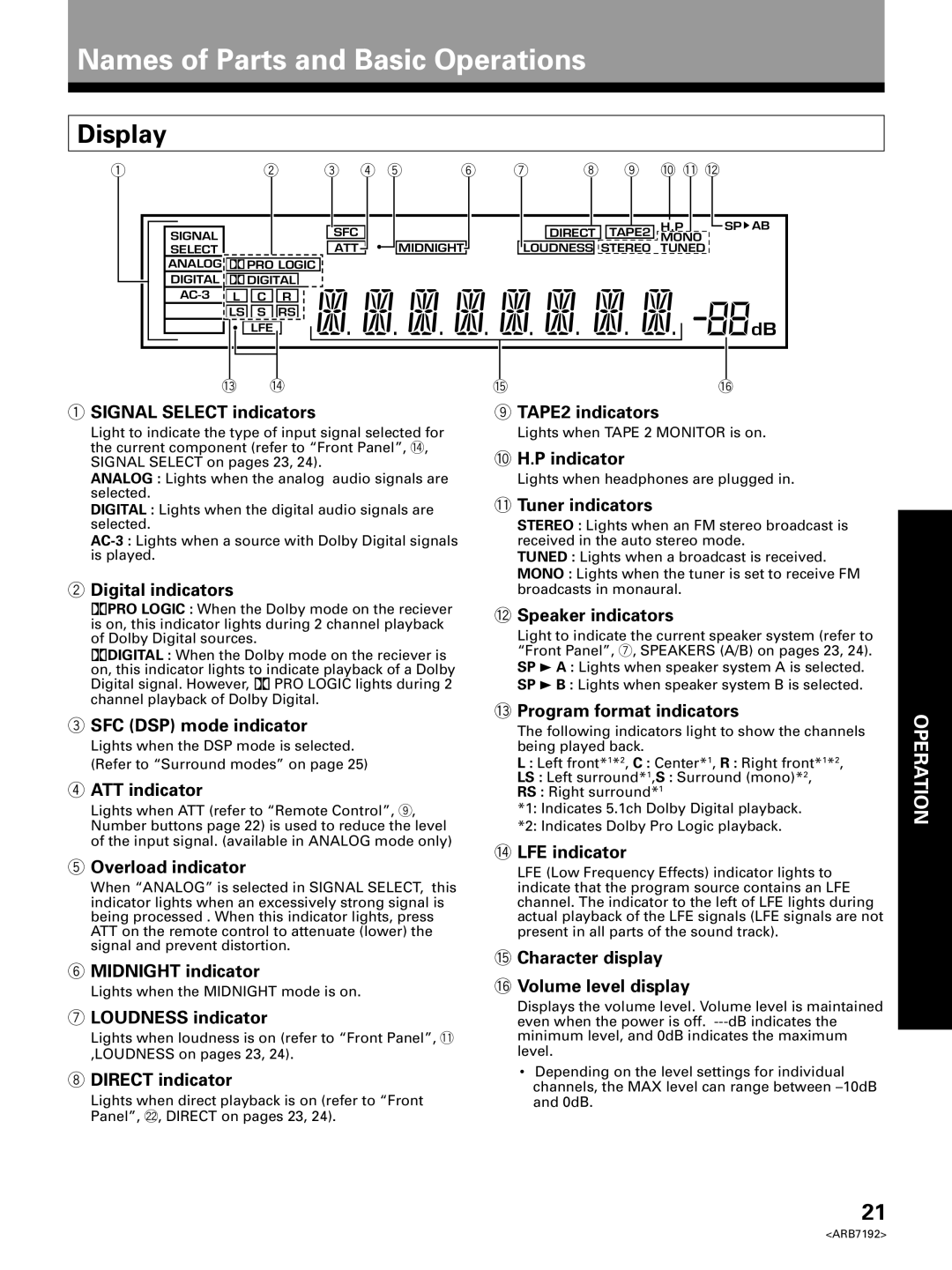
VSX-D498 Names of Parts and Basic Operations, Display, SIGNAL SELECT indicators
Models:
VSX-D498
1
21
48
48
Download
48 pages
31.46 Kb
18
19
20
21
22
23
24
25
Troubleshooting
Specification
Install
SIGNAL SELECT button
SIGNAL SELECT indicators
FM wire antenna
Symptom
Set Up Operation
6TUNING SELECT button
Setting Up for Surround Sound
Page 21
Image 21
Page 20
Page 22
Page 21
Image 21
Page 20
Page 22
Contents
VSX-D498
AUDIO/VIDEO MULTI-CHANNELRECEIVER
Operating Instructions
IMPORTANT NOTICE
Information to User
SET UP OPERATION
IMPORTANT SAFETY INSTRUCTIONS
DAMAGE REQUIRING SERVICE — Unplug this product
Dolby Digital and Dolby Pro Logic
Features
Various Surround Effects DSP
Midnight Listening Mode
Introductory Information
Table of Contents
Preparations
Names of Parts and Basic Operations
How to Use This Manual
Checking the Supplied Accessories
Power connection AC OUTLET
Preparing the Remote Control
When Making Cable Connections
Receiver Installation
Operating range of remote control unit
SET UP
Outdoor antenna Indoor antenna Vinyl-coatedwire
Using external antennas
Connections
Antennas
Audio Components Connections
Cassette deck placement
OPERATION
Connections
7 Front
Video Components Connections
7Audio/Video cords
Video deck
Digital Connections
When playing LD recorded in Dolby Digital
7Digital audio cords/Fiber-opticcables
Digital audio cord
Connections
DVD 5.1 Channel Connection
this unit to the AC power source
connections before connecting
Speakers
Amplified Sub Woofer
Sub Woofer FrontFront Left Center Right
Speaker placement
Surround
Left
1 Press RECEIVER STANDBY/ON to turn the power on
Setting Up for Surround Sound
4 Press % or fi to select the setting you desire
initial adjustments in the order described below
Front speaker initial setting is “L Large”
SPEAKER setting mode
Center speaker initial setting is “L Large”
Surround speaker initial setting is “L Large”
Crossover frequency setting mode
SUB WOOFER ON/OFF setting mode
LFE attenuator setting mode
• Initial setting is “0 dB”
FRONT speaker distance setting mode
Low cut filter ON/OFF setting mode
CENTER speaker distance setting mode
SURROUND speaker distance setting mode
Coaxial digital input setting
Dynamic range control setting mode
Optical digital input 1 setting
Optical digital input 2 setting
1 Press button
3 Press TEST TONE to output the test tone
5 Press TEST TONE to turn off the test tone
2Digital indicators
1 SIGNAL SELECT indicators
3SFC DSP mode indicator
4ATT indicator
9Number buttons/Surround setting buttons
Remote Control
=MASTER VOLUME+/–buttons
Names of Parts and Basic Operations
6TUNING SELECT button
2STANDBY indicator
Front Panel
1 STANDBY/ON button
$MASTER VOLUME
SIGNAL SELECT button
@DSP MODE button
#MIDNIGHT button
Surround modes
Sound Modes
Dolby Surround mode
DSP modes
Switching ANALOG/DIGITAL Signal Input
SIGNAL SELECT
Sound Modes
Playback
1 Turn on the power of the playback component
dB MIN to 0 dB MAX
OPERATION
5 Press VOL +/–to adjust the volume level
3 Press to switch the Dolby Surround mode on
Playing Sources with Dolby Digital Sound
DIGITAL
Surrround operation
Selecting a Sound Mode
Select the sound mode
=HALL 1 = HALL 2 = JAZZ = DANCE
Listening in MIDNIGHT Listening Mode
DVD 5.1ch Input Playback
Press DVD/LD on the unit
Press MIDNIGHT
Press TREBLE +/–to adjust the high frequencies
Press BASS +/–to adjust the low frequencies
TREBLE +/– BASS +/–
OPERATION
For Automatic Tuning
Automatic and Manual Tuning
For Manual Tuning
When using the front panel
To cancel before inputting the frequency
Direct Tuning
Tuner Operations
the remote to the tuner operation mode
32 4
Using the front panel
Memorizing Frequently Tuned Stations
1 Tune to the desired station
Recalling the Memorized Stations
Using the remote control
2 Press CLASS repeatedly to select a class
To skip through each channel in order
Recording from Audio Components
Other Operations
Record monitor TAPE 2 MONITOR
1 Select the component you want to record
Other Operations
Recording from Video Components
SIGNAL SELECT
OPERATION
DVD player operations
Remote Controlling Other PIONEER Components
44˜¢
51˜¡
pressing this button when the unit is stopped may
Press to switch the LD player on or off
LD player operations
4 4˜¢
2TV FUNC
TV operations
33 CHANNEL +/–
4 TV VOL. +/–
CD player operations
Press to switch the CD player on or off
7 CD DISC+/–
Press to stop playback
5 1˜¡
Cassette deck operations
7 Number buttons
7 button
Dolby Digital
Additional Information
Laser disc format
Comparison with Dolby Pro Logic Surround
Symptom
Troubleshooting
Additional Information
Cause
Additional Information
Symptom
Cause
Remedy
Amplifier Section
Specifications
AM Tuner Section
Miscellaneous
8 0 0 - 4 2 1 - 1 4
Maintenance of External Surfaces
Power cord CAUTION
• EIA
We Want You Listening For A Lifetime
Top
Page
Image
Contents