INSTALLATION/OPERATION
WARNING
During operation there is an open flame inside this appliance. The unit may get hot enough to set near by materials on fire. Keep the area around the appliance free from combustibles.
Lighting Instructions
For manual pilots, refer to the following instructions.
WARNING
If pilot extinguishes, wait 5 minutes before attempting to relight the pilot to allow any built
up gas to dissipate.
a. Open gas supply valves to the appliance.
b. Turn the thermostat control knob counterclockwise to the OFF position.
c.Turn the gas valve knob counterclockwise to the PILOT position. Push knob in and hold a flame to the pilot until the pilot ignites; this may take a little while the first time you light the pilot because of the air in the lines. Once lit, hold the knob in for approximately one minute and then release.
d.If the pilot goes out, wait 5 minutes and repeat step C. If after three tries the pilot will not remain lit, refer to the operator troubleshooting section of this manual.
e.Once a pilot flame has been established, turn the gas valve knob counterclockwise to the ON position.
f.Set the thermostat control knob to the desired temperature setting, The main burners will ignite and be controlled by the thermostat.
Pilot Flame Adjustment
For manual pilots, refer to the following instructions. Perform this procedure once the pilot is lit and ensure that the thermostat is turned to the OFF position.
NOTE: This procedure requires a DC millivolt meter set to a scale of
Using test leads with sharp probes will help in taking the required readings.
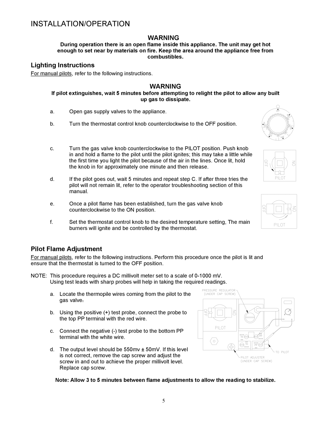
a. Locate the thermopile wires coming from the pilot to the gas valve.
b. Using the positive (+) test probe, connect the probe to the top PP terminal with the red wire.
c.Connect the negative
d. The output level should be 550mv ± 50mV. If this level is not correct, remove the cap screw and adjust the screw in and out to achieve the proper millivolt level. Replace cap screw.
Note: Allow 3 to 5 minutes between flame adjustments to allow the reading to stabilize.
5