4 Video Signal Requirements
4.1Video Input Lines
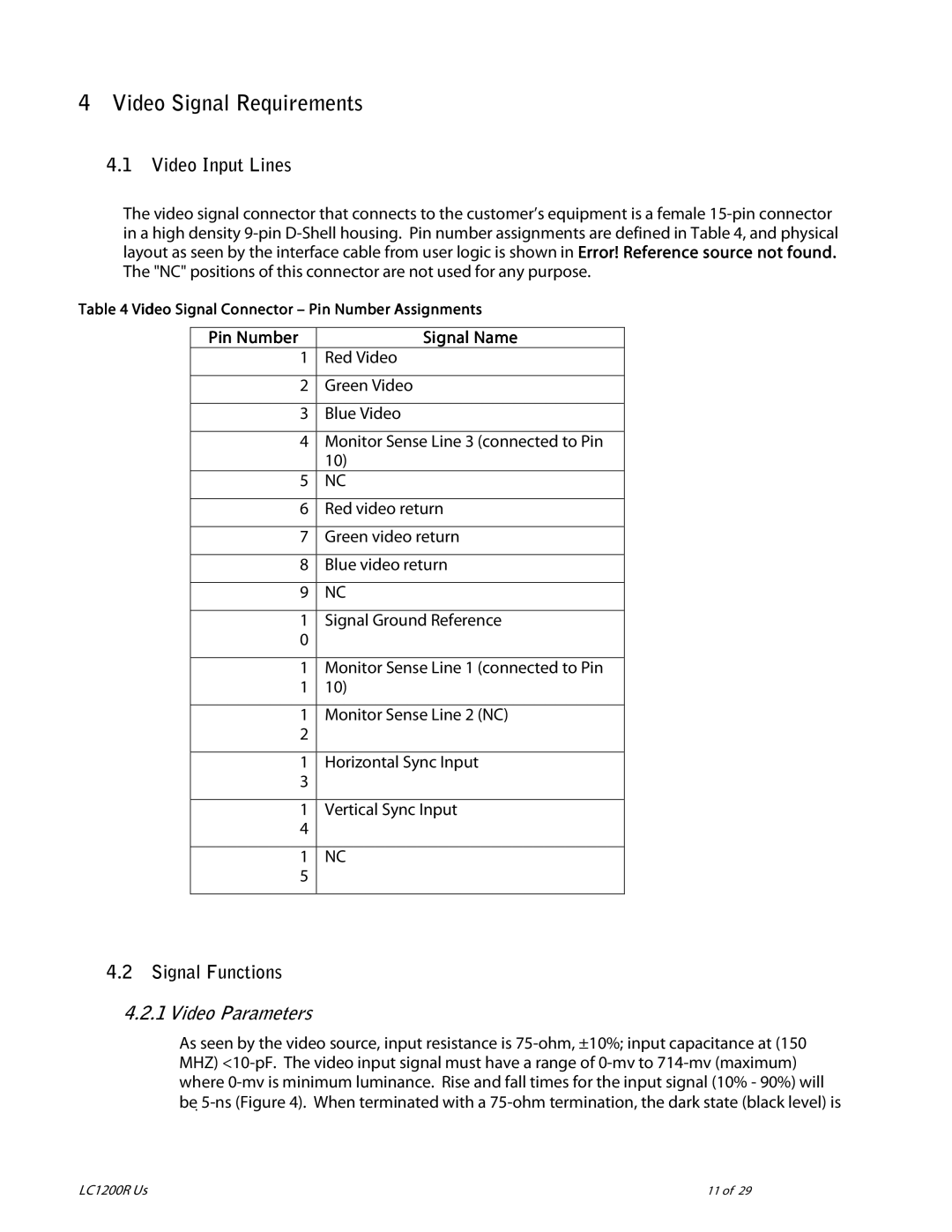
The video signal connector that connects to the customer’s equipment is a female
Table 4 Video Signal Connector – Pin Number Assignments
Pin Number | Signal Name |
1 | Red Video |
|
|
2 | Green Video |
|
|
3 | Blue Video |
|
|
4 | Monitor Sense Line 3 (connected to Pin |
| 10) |
5 | NC |
|
|
6 | Red video return |
|
|
7 | Green video return |
|
|
8 | Blue video return |
|
|
9 | NC |
|
|
1 | Signal Ground Reference |
0 |
|
|
|
1 | Monitor Sense Line 1 (connected to Pin |
1 | 10) |
|
|
1 | Monitor Sense Line 2 (NC) |
2 |
|
|
|
1 | Horizontal Sync Input |
3 |
|
|
|
1 | Vertical Sync Input |
4 |
|
|
|
1 | NC |
5 |
|
|
|
4.2Signal Functions
4.2.1Video Parameters
As seen by the video source, input resistance is
LC1200R | 11 of 29 |