4.2.3 Mode Detection
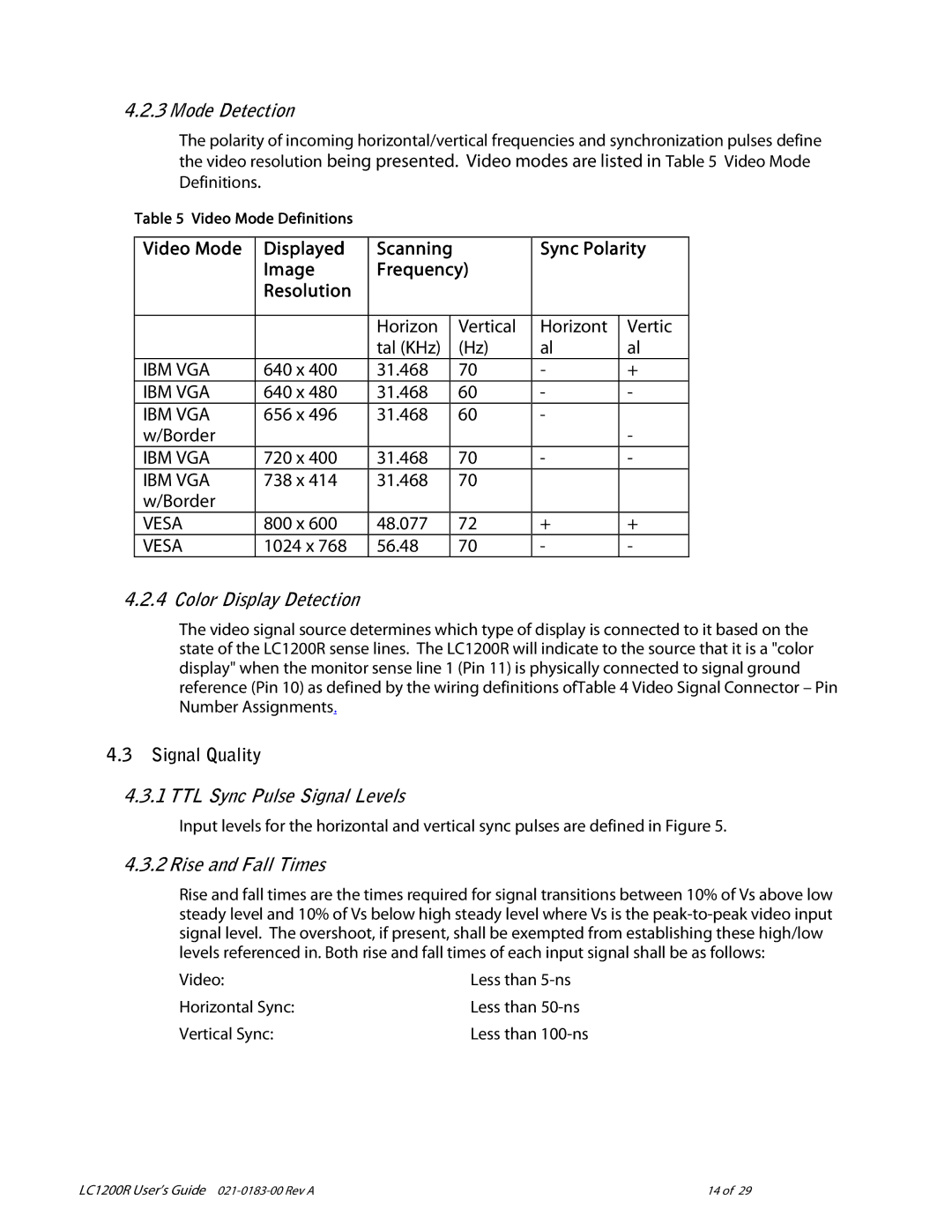
The polarity of incoming horizontal/vertical frequencies and synchronization pulses define the video resolution being presented. Video modes are listed in Table 5 Video Mode Definitions.
Table 5 Video Mode Definitions
Video Mode | Displayed | Scanning |
| Sync Polarity | ||
| Image | Frequency) |
|
| ||
| Resolution |
|
|
|
|
|
|
|
|
|
|
|
|
|
| Horizon |
| Vertical | Horizont | Vertic |
|
| tal (KHz) |
| (Hz) | al | al |
IBM VGA | 640 x 400 | 31.468 |
| 70 | - | + |
IBM VGA | 640 x 480 | 31.468 |
| 60 | - | - |
IBM VGA | 656 x 496 | 31.468 |
| 60 | - |
|
w/Border |
|
|
|
|
| - |
IBM VGA | 720 x 400 | 31.468 |
| 70 | - | - |
IBM VGA | 738 x 414 | 31.468 |
| 70 |
|
|
w/Border |
|
|
|
|
|
|
VESA | 800 x 600 | 48.077 |
| 72 | + | + |
VESA | 1024 x 768 | 56.48 |
| 70 | - | - |
4.2.4 Color Display Detection
The video signal source determines which type of display is connected to it based on the state of the LC1200R sense lines. The LC1200R will indicate to the source that it is a "color display" when the monitor sense line 1 (Pin 11) is physically connected to signal ground reference (Pin 10) as defined by the wiring definitions ofTable 4 Video Signal Connector – Pin Number Assignments.
4.3Signal Quality
4.3.1TTL Sync Pulse Signal Levels
Input levels for the horizontal and vertical sync pulses are defined in Figure 5.
4.3.2 Rise and Fall Times
Rise and fall times are the times required for signal transitions between 10% of Vs above low steady level and 10% of Vs below high steady level where Vs is the
Video: | Less than |
Horizontal Sync: | Less than |
Vertical Sync: | Less than |
LC1200R User’s Guide | 14 of 29 |