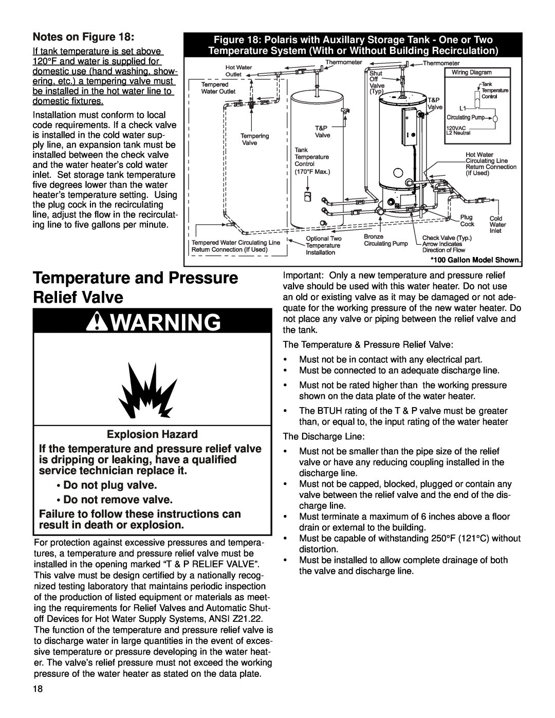
Notes on Figure 18: | Figure 18: Polaris with Auxillary Storage Tank - One or Two | |
If tank temperature is set above | Temperature System (With or Without Building Recirculation) | |
120°F and water is supplied for |
|
|
domestic use (hand washing, show- |
|
|
ering, etc.) a tempering valve must |
|
|
be installed in the hot water line to |
|
|
domestic fixtures. |
|
|
Installation must conform to local |
|
|
code requirements. If a check valve |
|
|
is installed in the cold water sup- |
|
|
ply line, an expansion tank must be |
|
|
installed between the check valve |
|
|
and the water heater’s cold water |
|
|
inlet. Set storage tank temperature |
|
|
five degrees lower than the water |
|
|
heater’s temperature setting. Using |
|
|
the plug cock in the recirculating |
|
|
line, adjust the flow in the recirculat- |
|
|
ing line to five gallons per minute. |
|
|
Temperature and Pressure | *100 Gallon Model Shown. | |
valve should be used with this water heater. Do not use | ||
Relief Valve |
| Important: Only a new temperature and pressure relief |
| an old or existing valve as it may be damaged or not ade- | |
|
| |
|
| quate for the working pressure of the new water heater. Do |
|
| not place any valve or piping between the relief valve and |
|
| the tank. |
The Temperature & Pressure Relief Valve:
| • Must not be in contact with any electrical part. | ||
| • Must be connected to an adequate discharge line. | ||
| • | Must not be rated higher than the working pressure | |
|
| shown on the data plate of the water heater. | |
| • The BTUH rating of the T & P valve must be greater | ||
|
| than, or equal to, the input rating of the water heater | |
Explosion Hazard | The Discharge Line: | ||
If the temperature and pressure relief valve | • | Must not be smaller than the pipe size of the relief | |
is dripping or leaking, have a qualified |
| valve or have any reducing coupling installed in the | |
service technician replace it. |
| discharge line. | |
• Do not plug valve. | • | Must not be capped, blocked, plugged or contain any | |
• Do not remove valve. |
| valve between the relief valve and the end of the dis- | |
| charge line. | ||
Failure to follow these instructions can |
| ||
• | Must terminate a maximum of 6 inches above a floor | ||
result in death or explosion. |
| drain or external to the building. | |
| • Must be capable of withstanding 250°F (121°C) without | ||
For protection against excessive pressures and tempera- | |||
| distortion. | ||
tures, a temperature and pressure relief valve must be |
| ||
• | Must be installed to allow complete drainage of both | ||
installed in the opening marked “T & P RELIEF VALVE”. | |||
This valve must be design certified by a nationally recog- | the valve and discharge line. |
| |
nized testing laboratory that maintains periodic inspection |
|
of the production of listed equipment or materials as meet- |
|
ing the requirements for Relief Valves and Automatic Shut- |
|
off Devices for Hot Water Supply Systems, ANSI Z21.22. |
|
The function of the temperature and pressure relief valve is |
|
to discharge water in large quantities in the event of exces- |
|
sive temperature or pressure developing in the water heat- |
|
er. The valve’s relief pressure must not exceed the working |
|
pressure of the water heater as stated on the data plate. |
|
18