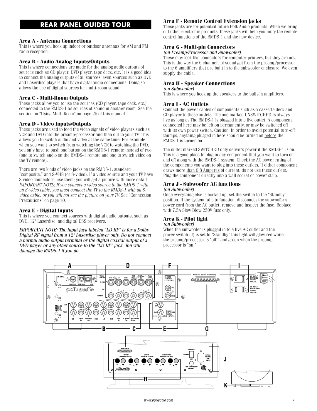
REAR PANEL GUIDED TOUR
Area A - Antenna Connections
This is where you hook up indoor or outdoor antennas for AM and FM radio reception.
Area B - Audio Analog Inputs/Outputs
This is where connections are made for the analog audio outputs of sources such as CD player, DVD player, tape deck, etc. It is a good idea to connect the analog outputs of all sources, even sources such as DVD and Laserdisc players that have digital audio connections. Doing so allows the use of digital sources for
Area C - Multi-Room Outputs
These jacks allow you to use the sources (CD player, tape deck, etc.) connected to the
Area D - Video Inputs/Outputs
These jacks are used to feed the video signals of video players such as VCR and DVD into the preamp/processor and then out to your TV. This allows you to switch audio and video at the same time. For example, when you want to switch from watching the VCR to watching the DVD, you only have to push one button on the
There are two kinds of video jacks on the
Area E - Digital Inputs
This is where you connect sources with digital audio outputs, such as DVD, 12" Laserdisc, and digital DSS receivers.
IMPORTANT NOTE: The input jack labeled “LD RF” is for a Dolby Digital RF signal from a 12" Laserdisc player only. Do not connect a normal audio output terminal or the digital coaxial output of a DVD player or any other source to the “LD RF” jack. You will damage the
Area F - Remote Control Extension jacks
These jacks are for potential future Polk Audio products. When we bring out other electronic products, these jacks will help you unify the remote control functions of the
Area G - Multi-pin Connectors
(on Preamp/Processor and Subwoofer)
These may look like connectors for computer printers, but they are not. This is the way the 6 channels of sound get from the preamp/processor to the 6 amplifiers that are built in to the subwoofer enclosure. We even supply the cable.
Area H - Speaker Connections
(on Subwoofer)
This is where you hook up the speakers to the
Area I - AC Outlets
Connect the power cables of components such as a cassette deck and CD player to these outlets. The one marked UNSWITCHED is always live as long as The
The outlet marked SWITCHED only delivers power if the
Area J - Subwoofer AC functions
(on Subwoofer)
Once everything else is hooked up, set the switch to the “Standby” position. If the system fails to function, disconnect the subwoofer’s power cord from the AC outlet, remove and inspect the fuse. Replace with 7.5A Slow Blow 250V fuse only.
Area K - Pilot light
(on Subwoofer)
When the subwoofer is plugged in to a live AC outlet and the power switch (J) is set to “Standby” this light will glow red while the preamp/processor is “off,” and green when the preamp processor is “on.”
|
|
|
| VIDEO |
|
|
| VCR | VCR Rec. | Video | AUDIO OUT (connect to subwoofer) |
ANTENNA |
|
|
|
|
| REMOTE | |||||
|
| INPUTS | DSS | LD | DVD | Input | Out | TV out | |||
|
|
|
| CONTROL | |||||||
|
|
|
|
|
|
|
|
|
| EXTENSION | |
| FM(75Ω |
|
|
|
|
|
|
|
|
| |
| ) | GROUND | AM |
|
|
|
|
|
|
| |
|
|
|
| OR |
|
|
|
|
|
| (in) |
|
|
|
|
|
|
|
|
|
|
| |
|
|
|
| Standard |
|
|
|
|
|
| (out) |
| Left |
|
|
|
|
|
|
|
| LD |
|
ANALOG |
|
|
|
|
|
|
|
| RF |
| |
AUDIO |
|
|
|
|
|
|
|
|
|
|
|
INPUTS | Right |
|
|
|
|
|
|
|
| DVD | DSS |
|
|
|
|
|
|
|
|
| |||
|
|
|
|
|
|
|
|
|
| D I G I T A L A U D I O I N P U T S | |
CD | TAPE | TAPE Rec. DSS | LD | DVD | VCR | VCR Rec. | |
| In | Out |
|
| In | Out | Output |
|
|
|
|
AUDIO INPUT |
|
|
|
|
FRONT |
| CENTER | SURROUND |
|
SPEAKER OUTPUT |
| SPEAKER OUTPUT | SPEAKER OUTPUT |
|
L | R |
| L | R |
|
| H |
|
|
AC OUTLET SWITCHED
120V,60HZ
100W,0.8A
AC OUTLET UNSWITCHED
120V,60HZ
100W,0.8A
www.polkaudio.com | 7 |