Installing SoundPoint® IP 500 SIP
This section provides basic installation instructions and information for obtaining the best performance with the SoundPoint IP 500 SIP telephone. If you require addi- tional information or assistance with your new telephone, please contact your System Administrator.
The SoundPoint IP 500 SIP User Guide includes regulatory compliance infor- mation that your System Administrator should review and can also be found at http://www.polycom.com.
Connecting Network and Power Source
AC Power Option
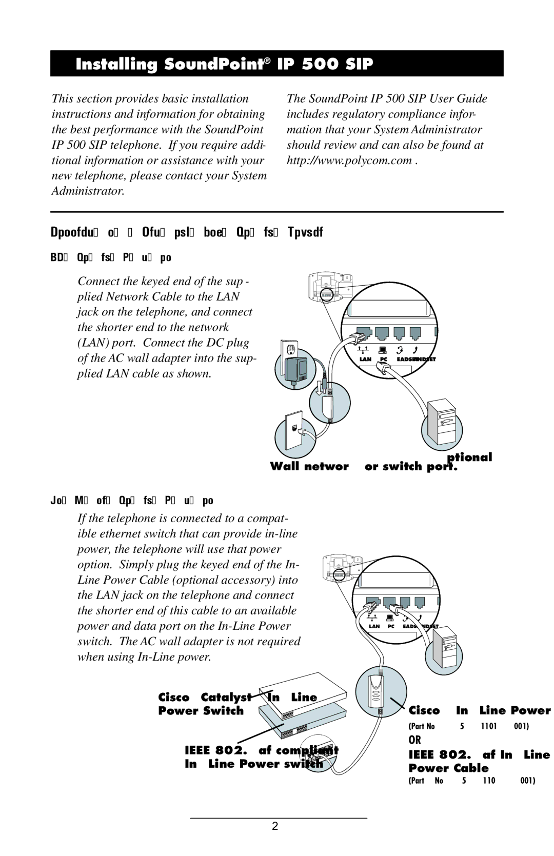
Connect the keyed end of the sup- plied Network Cable to the LAN jack on the telephone, and connect the shorter end to the network (LAN) port. Connect the DC plug of the AC wall adapter into the sup- plied LAN cable as shown.
LAN | PC | HEADSET HANDSET |
Wall network or switch port.
(Optional)
In-Line Power Option
If the telephone is connected to a compat- ible ethernet switch that can provide
Cisco™Catalyst™ ![]()
Power Switch
IEEE 802.3af compliant
LAN | PC | HEADSET HANDSET |
![]() Cisco™
Cisco™
(Part
OR
IEEE 802.3af
Power Cable
(Part. No
2