INTRODUCTION
Thank you for choosing the SoundStation Wireless Microphone System. This system operates on a
CHECKLIST OF PARTS
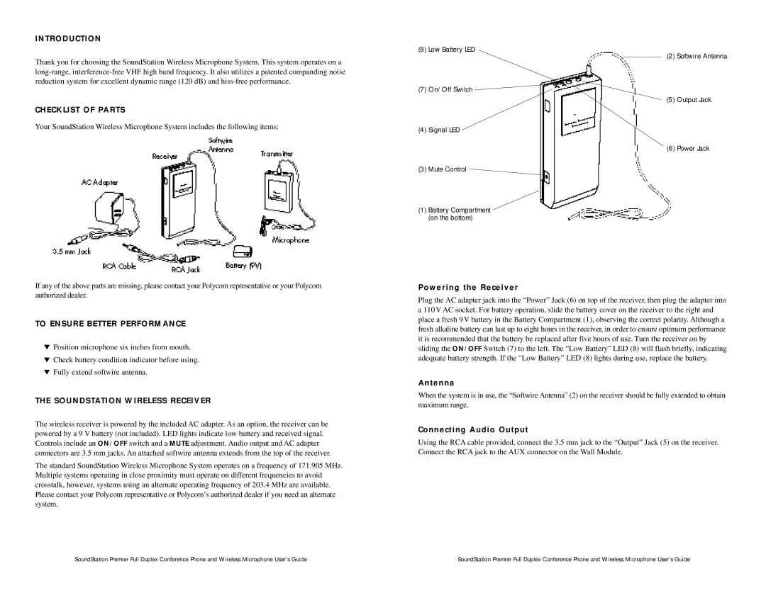
Your SoundStation Wireless Microphone System includes the following items:
If any of the above parts are missing, please contact your Polycom representative or your Polycom authorized dealer.
TO ENSURE BETTER PERFORMANCE
▼Position microphone six inches from mouth.
▼Check battery condition indicator before using.
▼Fully extend softwire antenna.
THE SOUNDSTATION WIRELESS RECEIVER
The wireless receiver is powered by the included AC adapter. As an option, the receiver can be powered by a 9 V battery (not included). LED lights indicate low battery and received signal. Controls include an ON/OFF switch and a MUTE adjustment. Audio output and AC adapter connectors are 3.5 mm jacks. An attached softwire antenna extends from the top of the receiver.
The standard SoundStation Wireless Microphone System operates on a frequency of 171.905 MHz. Multiple systems operating in close proximity must operate on different frequencies to avoid crosstalk, however, systems using an alternate operating frequency of 203.4 MHz are available. Please contact your Polycom representative or Polycom’s authorized dealer if you need an alternate system.
(8) Low Battery LED
(2) Softwire Antenna
(7) On/Off Switch
(5) Output Jack
(4) Signal LED
(6) Power Jack
(3) Mute Control ![]()
(1)Battery Compartment (on the bottom)
Powering the Receiver
Plug the AC adapter jack into the “Power” Jack (6) on top of the receiver, then plug the adapter into a 110V AC socket. For battery operation, slide the battery cover on the receiver to the right and place a fresh 9V battery in the Battery Compartment (1), observing the correct polarity. Although a fresh alkaline battery can last up to eight hours in the receiver, in order to ensure optimum performance it is recommended that the battery be replaced after five hours of use. Turn the receiver on by sliding the ON/OFF Switch (7) to the left. The “Low Battery” LED (8) will flash briefly, indicating adequate battery strength. If the “Low Battery” LED (8) lights during use, replace the battery.
Antenna
When the system is in use, the “Softwire Antenna” (2) on the receiver should be fully extended to obtain maximum range.
Connecting Audio Output
Using the RCA cable provided, connect the 3.5 mm jack to the “Output” Jack (5) on the receiver. Connect the RCA jack to the AUX connector on the Wall Module.
SoundStation Premier Full Duplex Conference Phone and Wireless Microphone User’s Guide | SoundStation Premier Full Duplex Conference Phone and Wireless Microphone User’s Guide |
