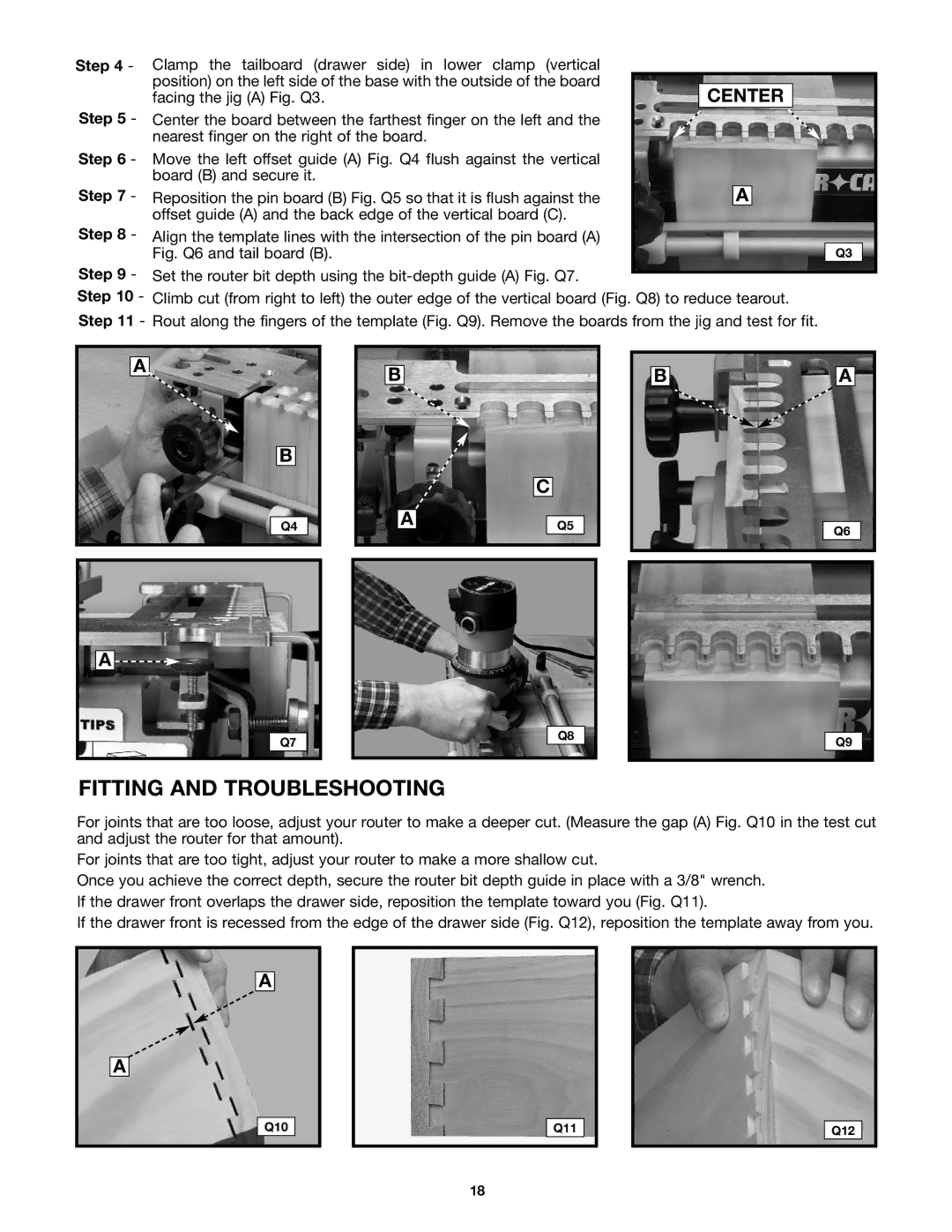
Step 4 - | Clamp the tailboard (drawer side) in lower clamp (vertical |
|
|
|
|
|
|
|
| position) on the left side of the base with the outside of the board |
|
|
|
|
|
|
|
| facing the jig (A) Fig. Q3. |
| CENTER |
|
|
| ||
Step 5 - | Center the board between the farthest finger on the left and the |
|
|
|
|
|
|
|
| nearest finger on the right of the board. |
|
|
|
|
|
|
|
Step 6 - | Move the left offset guide (A) Fig. Q4 flush against the vertical |
|
|
|
|
|
|
|
| board (B) and secure it. |
|
|
|
|
|
|
|
Step 7 - |
|
|
|
|
|
|
| |
Reposition the pin board (B) Fig. Q5 so that it is flush against the |
|
| A | |||||
| offset guide (A) and the back edge of the vertical board (C). |
|
|
|
|
|
|
|
Step 8 - | Align the template lines with the intersection of the pin board (A) |
|
|
|
|
|
|
|
| Fig. Q6 and tail board (B). |
|
|
|
|
| Q3 |
|
Step 9 -
Step 10 -
Step 11 - Rout along the fingers of the template (Fig. Q9). Remove the boards from the jig and test for fit.
A
B
Q4
B
A
C
Q5
B | A |
| Q6 |
A ![]()
Q7
Q8
Q9
FITTING AND TROUBLESHOOTING
For joints that are too loose, adjust your router to make a deeper cut. (Measure the gap (A) Fig. Q10 in the test cut and adjust the router for that amount).
For joints that are too tight, adjust your router to make a more shallow cut.
Once you achieve the correct depth, secure the router bit depth guide in place with a 3/8" wrench. If the drawer front overlaps the drawer side, reposition the template toward you (Fig. Q11).
If the drawer front is recessed from the edge of the drawer side (Fig. Q12), reposition the template away from you.
A
A
Q10
Q11
Q12
18
