INSTALLATION
Location of the Air Compressor
•Locate the air compressor in a clean, dry, and well ventilated area.
•Located the air compressor at least 12" away from the wall or other obstruc- tions that will interfere with the flow of air.
•Locate the air compressor as close to the main power supply as possible to avoid using long lengths of electrical wiring. Long lengths of electrical wiring could cause power loss to the motor.
•The air filter must be kept clear of obstructions which could reduce air flow to the air compressor.
Anchoring of the Air Compressor
Excessive Vibration can weaken the air tank and cause an explosion. The compressor must be properly
mounted.
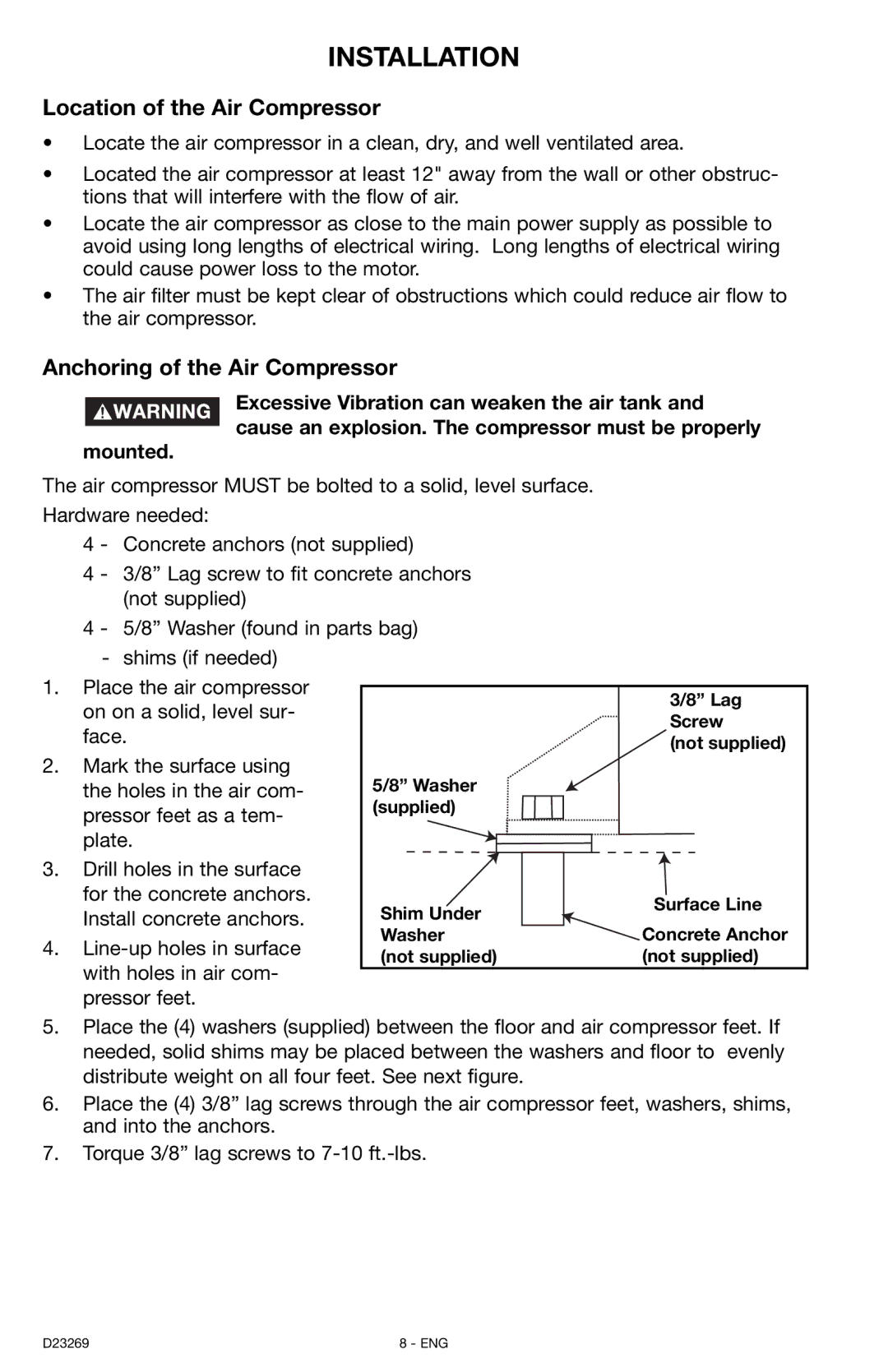
The air compressor MUST be bolted to a solid, level surface.
Hardware needed:
4 - Concrete anchors (not supplied)
4 - 3/8” Lag screw to fit concrete anchors (not supplied)
4 - 5/8” Washer (found in parts bag)
- shims (if needed)
1. | Place the air compressor |
|
|
|
|
|
| |
|
|
| 3/8” Lag |
| ||||
| on on a solid, level sur- |
|
|
|
| |||
|
|
|
| Screw |
| |||
| face. |
|
|
|
| |||
|
|
|
| (not supplied) |
| |||
2. | Mark the surface using | 5/8” Washer |
|
|
|
|
| |
|
|
|
|
| ||||
| the holes in the air com- |
|
|
|
|
| ||
| pressor feet as a tem- | (supplied) |
|
|
|
|
| |
|
|
|
|
|
|
| ||
| plate. |
|
|
|
|
|
| |
3. | Drill holes in the surface |
|
|
|
|
|
| |
| for the concrete anchors. |
|
|
|
|
|
| |
| Shim Under |
| Surface Line |
|
| |||
| Install concrete anchors. |
|
| |||||
|
|
|
|
|
| |||
| Washer | Concrete Anchor | ||||||
4. | ||||||||
(not supplied) | (not supplied) | |||||||
| with holes in air com- | |||||||
|
|
|
|
|
|
| ||
| pressor feet. |
|
|
|
|
|
| |
5.Place the (4) washers (supplied) between the floor and air compressor feet. If needed, solid shims may be placed between the washers and floor to evenly distribute weight on all four feet. See next figure.
6.Place the (4) 3/8” lag screws through the air compressor feet, washers, shims, and into the anchors.
7.Torque 3/8” lag screws to
D23269 | 8 - ENG |