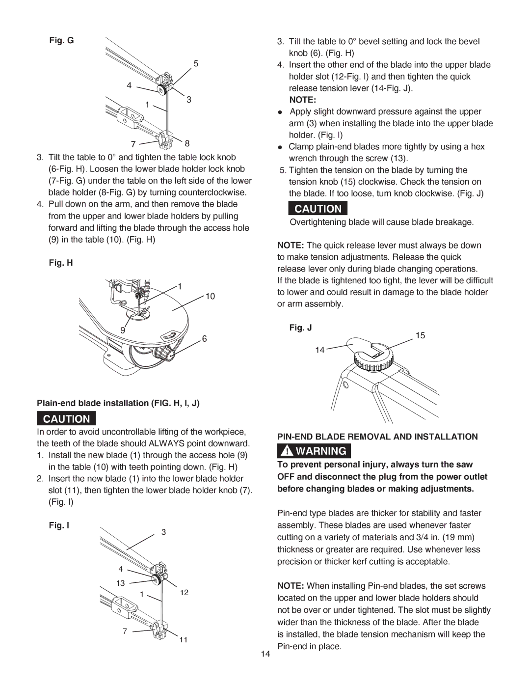
Fig. G
5
4
1 3
7![]()
![]()
![]()
![]()
![]()
![]()
![]()
![]()
![]() 8
8
3.Tilt the table to 0° and tighten the table lock knob
4.Pull down on the arm, and then remove the blade from the upper and lower blade holders by pulling forward and lifting the blade through the access hole
(9)in the table (10). (Fig. H)
Fig. H
1
10
9
6
3.Tilt the table to 0° bevel setting and lock the bevel knob (6). (Fig. H)
4.Insert the other end of the blade into the upper blade holder slot
NOTE:
●Apply slight downward pressure against the upper arm (3) when installing the blade into the upper blade holder. (Fig. I)
●Clamp
5.Tighten the tension on the blade by turning the tension knob (15) clockwise. Check the tension on the blade. If too loose, turn knob clockwise. (Fig. J)
CAUTION
Overtightening blade will cause blade breakage.
NOTE: The quick release lever must always be down to make tension adjustments. Release the quick release lever only during blade changing operations.
If the blade is tightened too tight, the lever will be difficult to lower and could result in damage to the blade holder or arm assembly.
Fig. J
15
Plain-end blade installation (FIG. H, I, J)
CAUTION
In order to avoid uncontrollable lifting of the workpiece, the teeth of the blade should ALWAYS point downward. 1. Install the new blade (1) through the access hole (9) in the table (10) with teeth pointing down. (Fig. H)
2. Insert the new blade (1) into the lower blade holder slot (11), then tighten the lower blade holder knob (7). (Fig. I)
Fig. I
3
4
13
1 12
7
11
14
14 ![]()
![]()
![]()
![]()
![]()
PIN-END BLADE REMOVAL AND INSTALLATION
!WARNING
To prevent personal injury, always turn the saw OFF and disconnect the plug from the power outlet before changing blades or making adjustments.
NOTE: When installing