MOUNTING SCROLL SAW TO WORK SURFACE (FIG. C)
1.If mounting the scroll saw to a workbench, a solid wood bench is preferred over a plywood board to reduce noise and vibration.
2.The hardware to mount this saw is NOT supplied with the saw. The hardware as shown in Fig. C should be used:
Fig. C
1
2
|
| 3 |
|
|
| 2 | 5 |
|
| 4 | |
1. | (3) | 6 | |
Hex head bolts; length as required | |||
2. | (6) | Flat washers |
|
3. | Foam pad or carpet (optional) | ||
4. | (3) | Lock washers |
|
5. | (3) | Hex nuts |
|
6. | (3) | Jam nuts |
|
BLADE STORAGE (FIG. D)
Blade storage is located on the left rear side of the scroll saw body. Pull out the blade storage door (1) to open. The compartment can conveniently store your hex wrenches and both
Fig. D
1
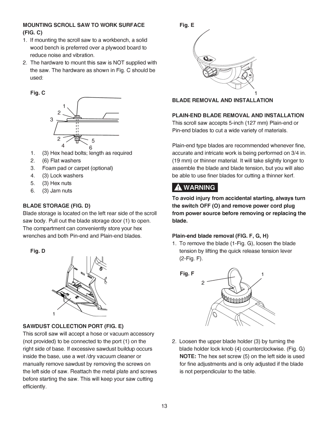
SAWDUST COLLECTION PORT (FIG. E)
This scroll saw will accept a hose or vacuum accessory (not provided) to be connected to the port (1) on the right side of base. If excessive sawdust buildup occurs inside the base, use a wet /dry vacuum cleaner or manually remove sawdust by removing the screws on the left side of saw. Reattach the metal plate and screws before starting the saw. This will keep your saw cutting efficiently.
Fig. E
1
BLADE REMOVAL AND INSTALLATION
!WARNING
To avoid injury from accidental starting, always turn the switch OFF (O) and remove power cord plug from power source before removing or replacing the blade.
1.To remove the blade
Fig. F | 1 |
2
2.Loosen the upper blade holder (3) by turning the blade holder lock knob (4) counterclockwise. (Fig. G) NOTE: The hex set screw (5) on the left side is used for fine adjustments and is only adjusted if the blade is not perpendicular to the table.
13