Manuel d’instructions Manual de instrucciones
California Proposition
Table of Contents
Support and Clamp Work
Safety Guidelines Definitions
Prohibition
General Safety Instructions Before Using this Power Tool
Power Tool Safety
Bench Grinder Safety
Bench Grinder Safety
Guidelines for Extension Cords
Electrical Requirements and Safety
Power Supply and Motor Specifications
Grounding Instructions
Tools Needed for Assembly
Know Your Bench Grinder
Installing the EYE Shields FIG. E
Assembly and Adjustments
Installing Tool Rests FIG. A, B, C
Installing the Spark Guards FIG. D
Never USE a Grinding Wheel Without a Blotter
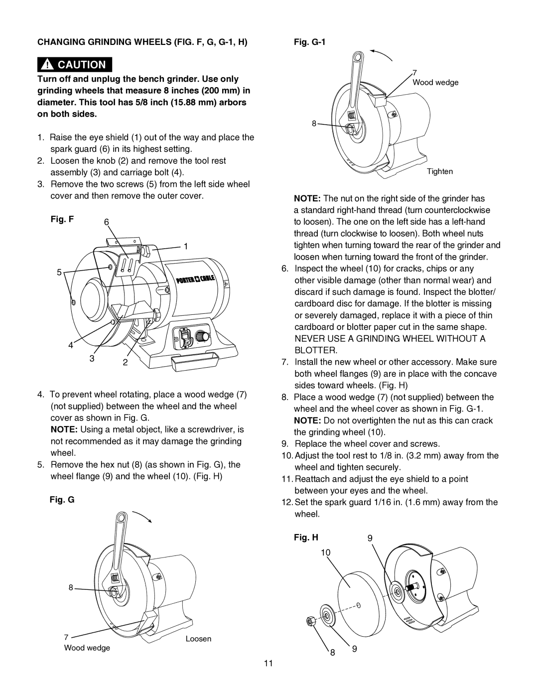
Changing Grinding Wheels FIG. F, G, G-1, H
Replacing the Bulb FIG
Installing the Coolant Tray FIG. J
Cooling Workpiece FIG. P
Using the Worklight FIG. N
Adjusting the Speed of Grinder FIG. O
Operation
Screwdrivers
General Operation
Scissors
Knives
General
Maintenance
Problem Problem Cause Suggested Corrective Action
Troubleshooting Guide
Replacement Parts Service and Repairs
Available Accessories
Accessories and Attachments
MM Variable Speed Grinder with Worklight Parts List
Parts List
MM Variable Speed Grinder with Worklight Schematic
Three Year Limited Warranty
Warranty
Advertencia Léase Este
Moteur Meule
Table DES Matières
Proposition 65 DE LA Californie
Soutenir ET Bien Serrer LES Pièces
Symboles D’AVERTISSEMENT
Mesures DE Sécurité Définitions
Interdiction
Toujours Porter DES Lunettes DE
Consignes DE Sécurité Outil Électrique
NE PAS SE Pencher AU Dessus DE
Sécurité Pour LA Meuleuse SUR Pied
Directives DE Mise À LA Terre
Caractéristiques Électriques ET Sécurité
Boucliers Protecteurs ET Pareétincelles
Données Techniques SUR LE Moteur ET L’ALIMENTATION
Calibre Minimum DES Rallonges AWG
Directives Concernant LES Rallonges
Tableau DES Pièces Détachées ART Description Quantité
Déballage DE LA Meuleuse SUR Pied
Déballage ET Vérification DU Contenu
Parties DE LA Meuleuse SUR Pied
Installation DES Protecteurs Oculaires FIG. E
Installation DES Appuis D’OUTIL FIG. A, B, C
Installation DES PARE-ÉTINCELLES FIG. D
Remplacement DES Meules FIG. F, G, G-1, H
Fig. J
Installation DU BAC D’ARROSAGE FIG. J
Refroidissement DE LA Pièce FIG. P
Utilisation
Démarrage ET Arrêt DE LA Meuleuse FIG. M
Utilisation DE LA Lampe DE Travail FIG. N
Tournevis
Fonctionnement
Ciseaux
Couteaux
Généralités
Entretien
Guide DE Dépannage
Pièces DE Rechange Service APRÈS-VENTE ET Réparations
Problème Cause Probable Solution Conseillée
Accessoires Offerts EN Option
Accessoires
Liste DE Pièces
Liste DE Pièces
X4BC
Schéma
Remarque
Garantie Limitée DE Trois 3 ANS
Garantie
Número DE Catálogo PCB575BG
Sección Página
Índice
Especificaciones DEL Producto
Proposicion 65 DE California
Apoye LA Pieza DE Trabajo Y Asegurela CON Abrazaderas
Pautas DE SEGURIDAD/DEFINICIONES
Iconos DE Advertencia
Prohibido
Utilice LOS Accesorios Recomendados
Utilice Siempre Proteccion Para LOS Ojos
Seguridad EN EL Manejo DE Herramientas Eléctricas
Seguridad EN EL Manejo DE LA Moledora DE Banco
Instrucciones Para LA Conexión a Tierra
Requisitos Eléctricos Y Deseguridad
EN Caso DE QUE Alguna Pieza DE
Especificaciones DEL Suministro Eléctrico Y DEL Motor
Calibre Minimo Para Extensiones Electricas AWG
Extensiones Electricas
Tabla DE Piezas Sueltas Artículo Descripción Cantidad
Desempaque DE LA Moledora DE Banco
Desempaque Y Verificación DEL Contenido
Protector contra las chispas
Conozca SU Moledora DE Banco
Instalación DE LOS Protectores Para LOS Ojos FIG. E
Ensamble Y Ajustes
Instalacion DE LOS Soportes Para Herramientas FIG. A, B, C
Instalación DE LOS Protectores Contra Chispas FIG. D
Fig. F
Cambio DE LAS Muelas Abrasivas FIG. F, G, G-1, H
Almacenaje DE LA Herramienta
Reemplazo DEL Foco FIG
Instalación DE LA Bandeja DE Refrigerante FIG. J
Montaje DE LA Herramienta Sobre UN Banco DE Trabajo FIG. K
Ajuste DE Lavelocidad DE Laamoladora FIG. O
Funcionamiento
Como Encender Y Apagar LA Moledora FIG. M
USO DE LA LUZ DE Trabajo FIG. N
Destornilladores
Trabajos Generales
Tijeras
Cuchillos
Generales
Mantenimiento
Piezas DE Repuesto Servicio Y Reparaciones
Guia Para LA Solucion DE Problemas
Problema Causa DEL / Problema Acción Correctiva Sugerida
Accesorios Disponibles
Accesorios Y Acoplamientos
Lista DE Piezas
Lista DE Piezas
X4BC
Esquema
Nota
Garantia Limitada POR Tres AÑO
Garantía