C.Cable Connections
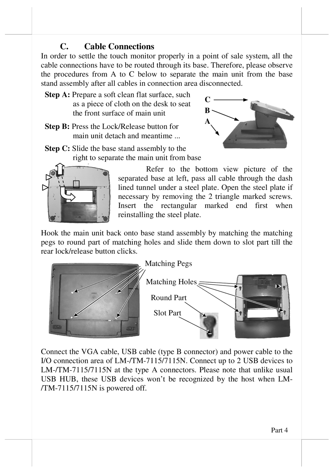
In order to settle the touch monitor properly in a point of sale system, all the cable connections have to be routed through its base. Therefore, please observe the procedures from A to C below to separate the main unit from the base stand assembly after all cables in connection area disconnected.
Step A: Prepare a soft clean flat surface, such | C | |
as a piece of cloth on the desk to seat | ||
B | ||
the front surface of main unit | ||
|
Step B: Press the Lock/Release button for
A
main unit detach and meantime ...
Step C: Slide the base stand assembly to the right to separate the main unit from base
Refer to the bottom view picture of the separated base at left, pass all cable through the dash lined tunnel under a steel plate. Open the steel plate if necessary by removing the 2 triangle marked screws. Insert the rectangular marked end first when reinstalling the steel plate.
Hook the main unit back onto base stand assembly by matching the matching pegs to round part of matching holes and slide them down to slot part till the rear lock/release button clicks.
Matching Pegs
Matching Holes![]()
Round Part
Slot Part ![]()
Connect the VGA cable, USB cable (type B connector) and power cable to the I/O connection area of
Part 4
