Blade Installation/Replacement
![]() Use care when working with or around sharp saw blade to prevent injury!
Use care when working with or around sharp saw blade to prevent injury!
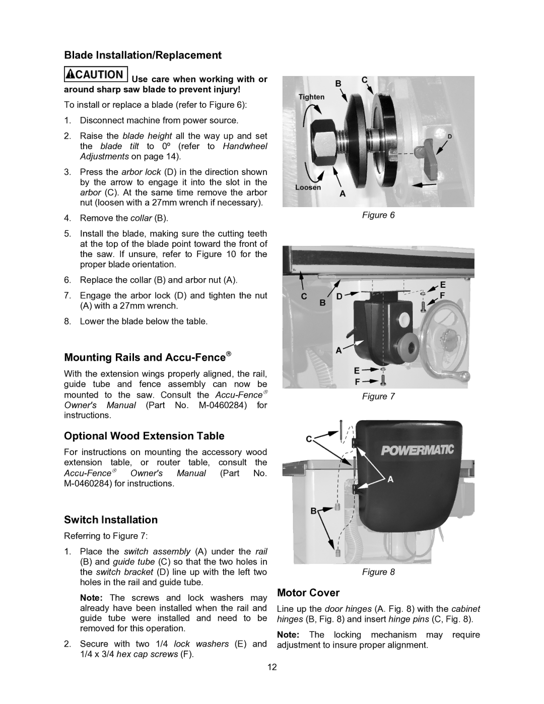
To install or replace a blade (refer to Figure 6):
1.Disconnect machine from power source.
2.Raise the blade height all the way up and set the blade tilt to 0º (refer to Handwheel Adjustments on page 14).
3.Press the arbor lock (D) in the direction shown by the arrow to engage it into the slot in the arbor (C). At the same time remove the arbor nut (loosen with a 27mm wrench if necessary).
4.Remove the collar (B).
5.Install the blade, making sure the cutting teeth at the top of the blade point toward the front of the saw. If unsure, refer to Figure 10 for the proper blade orientation.
6.Replace the collar (B) and arbor nut (A).
7.Engage the arbor lock (D) and tighten the nut
(A) with a 27mm wrench.
8.Lower the blade below the table.
Mounting Rails and
With the extension wings properly aligned, the rail, guide tube and fence assembly can now be mounted to the saw. Consult the
Optional Wood Extension Table
For instructions on mounting the accessory wood extension table, or router table, consult the
Figure 6
Figure 7
Switch Installation
Referring to Figure 7:
1.Place the switch assembly (A) under the rail
(B) and guide tube (C) so that the two holes in the switch bracket (D) line up with the left two holes in the rail and guide tube.
Note: The screws and lock washers may already have been installed when the rail and guide tube were installed and need to be removed for this operation.
2.Secure with two 1/4 lock washers (E) and 1/4 x 3/4 hex cap screws (F).
Figure 8
Motor Cover
Line up the door hinges (A. Fig. 8) with the cabinet hinges (B, Fig. 8) and insert hinge pins (C, Fig. 8).
Note: The locking mechanism may require adjustment to insure proper alignment.
12