Assembly
Mounting Extension Wings
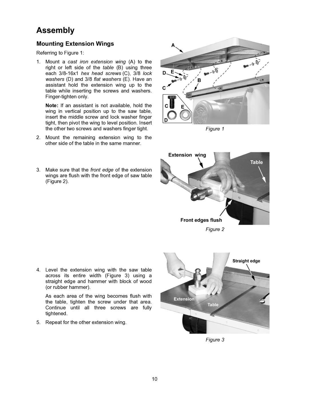
Referring to Figure 1:
1.Mount a cast iron extension wing (A) to the right or left side of the table (B) using three each
Note: If an assistant is not available, hold the wing in vertical position up to the saw table, insert the middle screw and lock washer finger tight, then pivot the wing to level position. Insert the other two screws and washers finger tight.
2.Mount the remaining extension wing to the other side of the table in the same manner.
3.Make sure that the front edge of the extension wings are flush with the front edge of saw table (Figure 2).
4.Level the extension wing with the saw table across its entire width (Figure 3) using a straight edge and hammer with block of wood (or rubber hammer).
As each area of the wing becomes flush with the table, tighten the screw under that area. Continue until all three screws are fully tightened.
5.Repeat for the other extension wing.
Figure 1
Figure 2
Figure 3
10