Riving Knife Adjustment
Lateral alignment
The saw blade and riving knife must be in line as close as possible with each other (lateral alignment) for the prevention of kickback. Upon initial blade guard and riving knife installation no further adjustment should be necessary. Alignment should be checked and adjusted, if required, after each blade change.
Check the alignment as follows:
1.Remove the blade guard and pawl (C, E, Fig. 9).
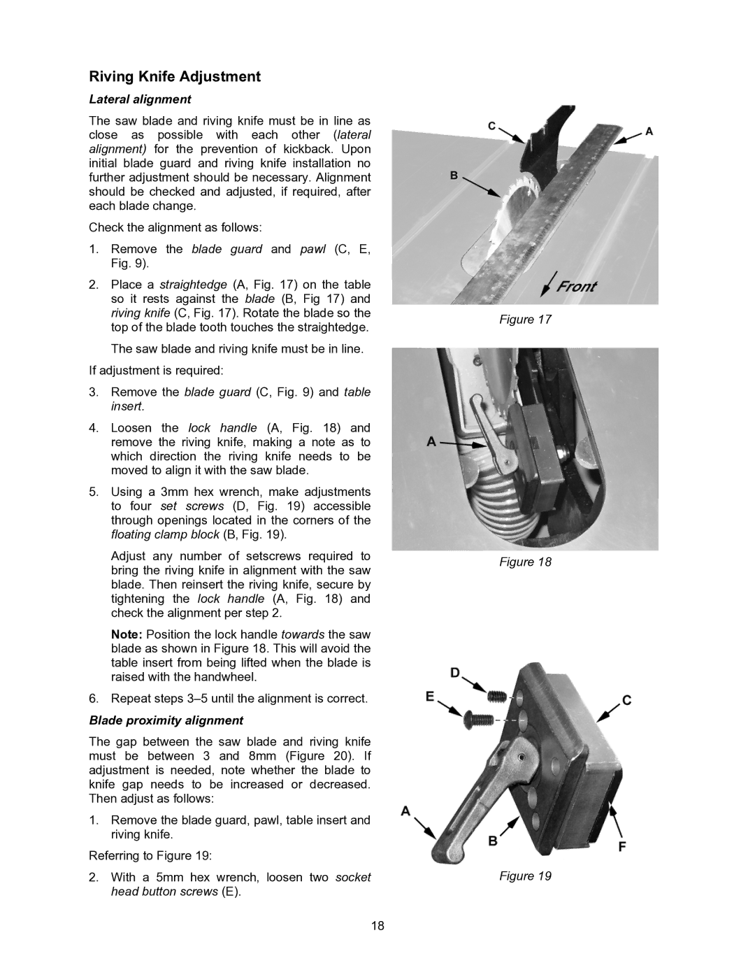
2.Place a straightedge (A, Fig. 17) on the table so it rests against the blade (B, Fig 17) and riving knife (C, Fig. 17). Rotate the blade so the top of the blade tooth touches the straightedge.
The saw blade and riving knife must be in line. If adjustment is required:
3.Remove the blade guard (C, Fig. 9) and table insert.
4.Loosen the lock handle (A, Fig. 18) and remove the riving knife, making a note as to which direction the riving knife needs to be moved to align it with the saw blade.
5.Using a 3mm hex wrench, make adjustments to four set screws (D, Fig. 19) accessible through openings located in the corners of the floating clamp block (B, Fig. 19).
Adjust any number of setscrews required to bring the riving knife in alignment with the saw blade. Then reinsert the riving knife, secure by tightening the lock handle (A, Fig. 18) and check the alignment per step 2.
Note: Position the lock handle towards the saw blade as shown in Figure 18. This will avoid the table insert from being lifted when the blade is raised with the handwheel.
6.Repeat steps
Blade proximity alignment
The gap between the saw blade and riving knife must be between 3 and 8mm (Figure 20). If adjustment is needed, note whether the blade to knife gap needs to be increased or decreased. Then adjust as follows:
1.Remove the blade guard, pawl, table insert and riving knife.
Referring to Figure 19:
2.With a 5mm hex wrench, loosen two socket head button screws (E).
18
Figure 17
Figure 18
Figure 19