Installation & Assembly
Tools required for assembly
forklift or hoist with straps/slings 11mm wrench (provided)
[NOTE: A socket set with ratchet wrench may speed assembly]
4 and 5mm hex wrenches (provided) knife or wire cutter
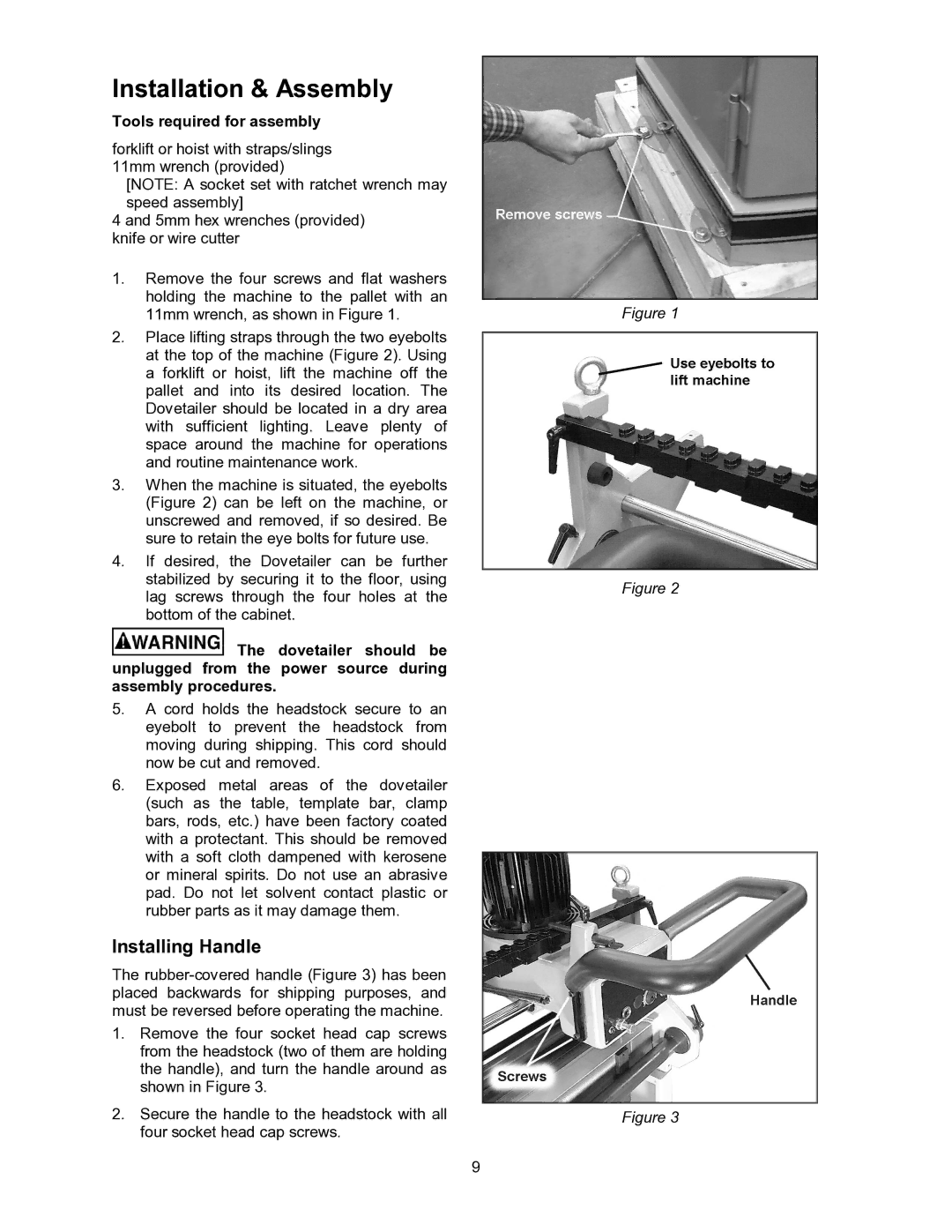
1.Remove the four screws and flat washers holding the machine to the pallet with an 11mm wrench, as shown in Figure 1.
2.Place lifting straps through the two eyebolts at the top of the machine (Figure 2). Using a forklift or hoist, lift the machine off the pallet and into its desired location. The Dovetailer should be located in a dry area with sufficient lighting. Leave plenty of space around the machine for operations and routine maintenance work.
3.When the machine is situated, the eyebolts (Figure 2) can be left on the machine, or unscrewed and removed, if so desired. Be sure to retain the eye bolts for future use.
4.If desired, the Dovetailer can be further stabilized by securing it to the floor, using lag screws through the four holes at the bottom of the cabinet.
![]() The dovetailer should be unplugged from the power source during assembly procedures.
The dovetailer should be unplugged from the power source during assembly procedures.
5.A cord holds the headstock secure to an eyebolt to prevent the headstock from moving during shipping. This cord should now be cut and removed.
6.Exposed metal areas of the dovetailer (such as the table, template bar, clamp bars, rods, etc.) have been factory coated with a protectant. This should be removed with a soft cloth dampened with kerosene or mineral spirits. Do not use an abrasive pad. Do not let solvent contact plastic or rubber parts as it may damage them.
Installing Handle
The
1.Remove the four socket head cap screws from the headstock (two of them are holding the handle), and turn the handle around as shown in Figure 3.
2.Secure the handle to the headstock with all four socket head cap screws.
9
Figure 1
Figure 2
Figure 3