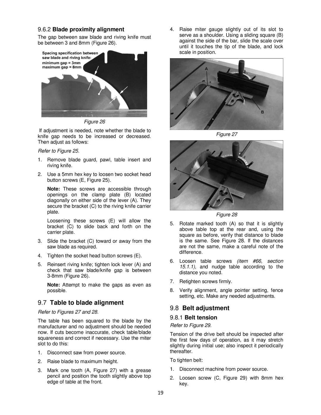
9.6.2Blade proximity alignment
The gap between saw blade and riving knife must be between 3 and 8mm (Figure 26).
Figure 26
If adjustment is needed, note whether the blade to knife gap needs to be increased or decreased. Then adjust as follows:
Refer to Figure 25.
1.Remove blade guard, pawl, table insert and riving knife.
2.Use a 5mm hex key to loosen two socket head button screws (E, Figure 25).
Note: These screws are accessible through openings on the clamp plate (B) located diagonally on either side of the lever (A). They secure the bracket (C) to the riving knife carrier plate.
Loosening these screws (E) will allow the bracket (C) to slide back and forth on the carrier plate.
3.Slide the bracket (C) toward or away from the saw blade as required.
4.Tighten the socket head button screws (E).
5.Reinsert riving knife; tighten lock lever (A) and check that saw blade/knife gap is between
Note: Attempt to make the gaps as even as possible.
9.7Table to blade alignment
Refer to Figures 27 and 28.
The table has been squared to the blade by the manufacturer and no adjustment should be needed now. If cuts become inaccurate, check table/blade squareness and correct if necessary. Use the miter slot to do this:
1.Disconnect saw from power source.
2.Raise blade to maximum height.
3.Mark one tooth (A, Figure 27) with a grease pencil and position the tooth slightly above top edge of table at the front.
4.Raise miter gauge slightly out of its slot to serve as a shoulder. Using a sliding square (B) against the side of the bar, slide the scale over until it touches the tip of the blade, and lock scale in position.
Figure 27
Figure 28
5.Rotate marked tooth (A) so that it is slightly above table top at the rear and, using the square as before, verify that distance to blade is the same. See Figure 28. If the distances are not the same, make a careful note of the difference.
6.Loosen table screws (item #66, section 15.1.1), and nudge table according to the distance you noted.
7.Retighten screws firmly.
8.Verify alignment, angle pointer setting, fence setting, etc. Make any needed adjustments.
9.8Belt adjustment
9.8.1Belt tension
Refer to Figure 29.
Tension of the drive belt should be inspected after the first few days of operation, as it may stretch slightly during initial use; also inspect it periodically thereafter.
To tighten belt:
1.Disconnect machine from power source.
2.Loosen screw (C, Figure 29) with 8mm hex key.
19